JAJU737A June 2019 – March 2020 AWR1243 , AWR2243
3.3.3 20 GHz Local Oscillator (LO) Distribution
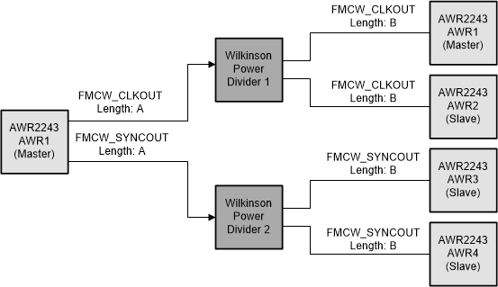
20-GHz LO distribution to all AWR2243 devices is accomplished through an entirely passive, transmission-line and etched power divider network. By using the dual LO outputs and LO inputs provided on each AWR2243 device, all devices including the master device, receive the same master device generated LO output. This results in all package and die routing delays common across all devices. The PCB designer is left with the task of delay matching only the BGA to BGA delays.
By using both of the 6-dBm (typical) LO output, and minimizing transmission line and power divider losses, no external amplifiers are required to be added to the LO network. Additionally, by outputting 20 GHz LO versus full 77-GHz RF for RF synchronization, the LO PCB link budgets can be more relaxed.
The passive LO distribution network and relaxed link budget results in more PCB design flexibility and a lower overall system cost.
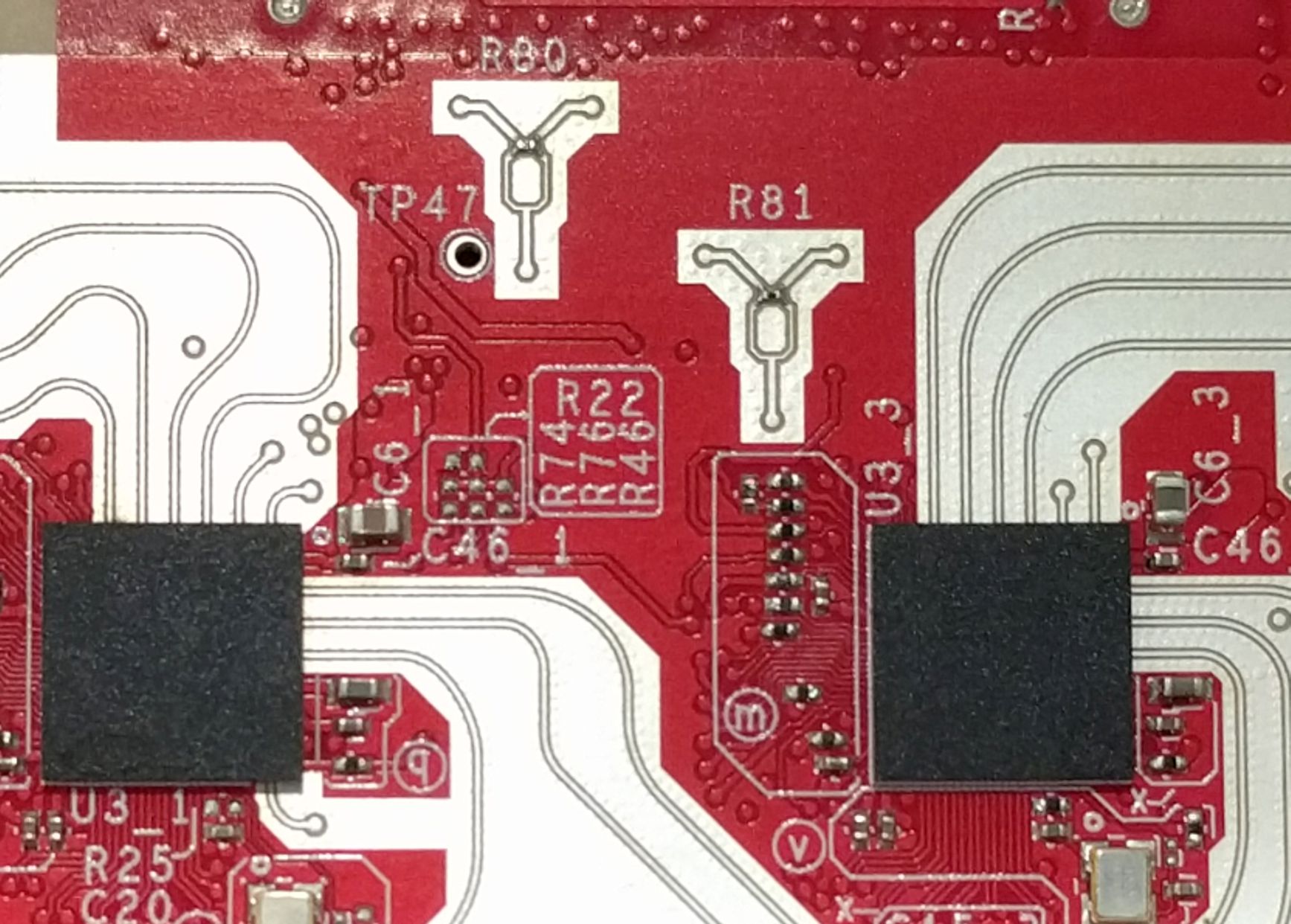
Figure 3 shows the block diagram of the delay matched LO distribution. Figure 4 shows the implemented Wilkinson power dividers in GCPW transmission-line. Fanout from the AWR2243 devices and power dividers is through GCPW lines. The majority of the LO distribution length is carried through an internal Stripline layer.

