JAJU791 April 2020
- 概要
- リソース
- 特長
- アプリケーション
- デザイン・イメージ
- 1System Overview
- 2LED Driver Key Parameters
- 3Layout
- 4Related Documentation
1.5 LED Driver SDIM/UDIM Settings
There are 2 control signals that can be options to turn LEDs on and off – UDIM and SDIM. UDIM controls the synchronous NFET operation of the buck regulator and provides for a slower turn on of the LEDs. SDIM turns off/on shunt NFET that quickly shunts current from and to the LED providing for faster rise time. SDIM rise time is x5 faster than UDIM. SDIM fall time is x20 times faster than UDIM. LED load, as well as capacitor that is placed in parallel with the load, can influence rise/fall time of the current (current rise/fall time vs. capacitor is addressed in Section 2.5)
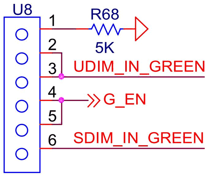
Each LED driver block has a connector that allows for flexibility of design in testing UDIM and SDIM operation. Current board is set up for SDIM operation.

Table 4. Default Jumpers
| OPTIONS | CONNECTOR SETTING | OTHER REQUIREMENTS |
|---|---|---|
| SDIM (Default) | Jumper together pin 5 and 6 | Shunt NFET must be populated |
| UDIM | Jumper together pin 4 and 3 | Shunt NFET must be depopulated |
NOTE
Warning: Make sure UDIM is driven to 0 V during power up, especially when main supply that drives LEDs is on. If UDIM is left floating, it will apply constant VLED voltage/current and might damage the LED, if LED is meant to be pulsed.