JAJU791 April 2020
- 概要
- リソース
- 特長
- アプリケーション
- デザイン・イメージ
- 1System Overview
- 2LED Driver Key Parameters
- 3Layout
- 4Related Documentation
1 System Overview
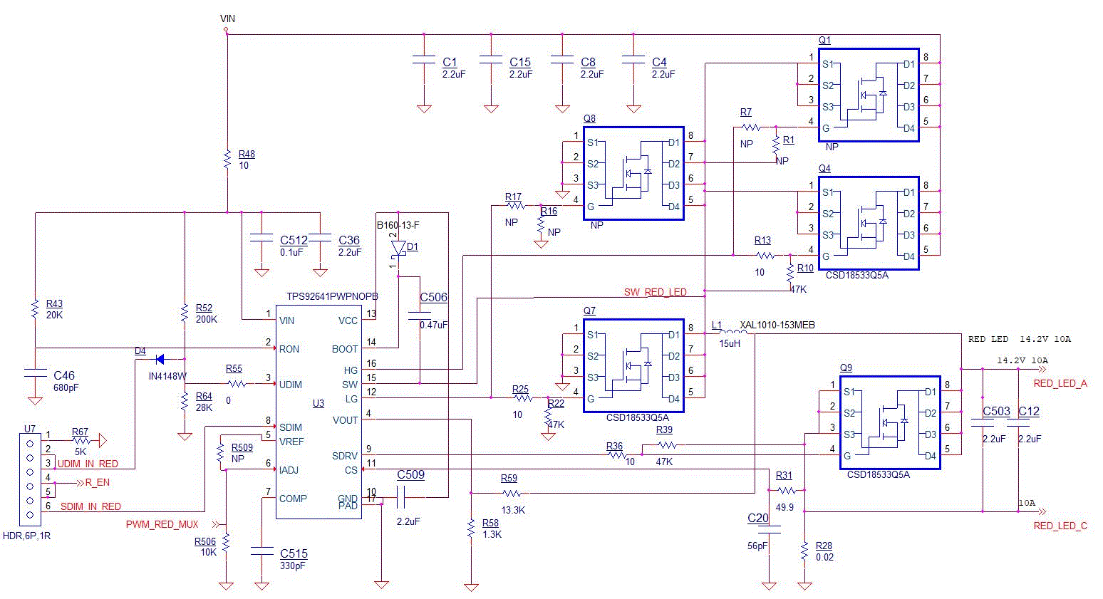
The TPS92641 is a high-voltage and synchronous NFET controller for buck-current regulators. Output current regulation is based on valley current-mode operation using on-time control architecture. This control method eases the loop compensation design and faster transient response. The PWM controller supports both analog and PWM input signals resulting in exceptional dimming control range. A linear dimmer between input command and LED current is achieved with true zero current using a low off-set error amplifier and proprietary PWM dimming logic. Protection features include cycle-by-cycle current protection, overvoltage protection, and thermal shutdown. LED driver has 3 separate driver blocks which allows for flexible color overlap schemes. As shown in Figure 1 the LED driver has 3 separate driver blocks, allowing for flexible color overlap schemes.
