JAJU791 April   2020


  1.    概要
  2.    リソース
  3.    特長
  4.    アプリケーション
  5.    デザイン・イメージ
  6. 1System Overview
    1. 1.1 Key System Specifications
    2. 1.2 Block Diagram
    3. 1.3 Top Side Pump
    4. 1.4 LED Driver Input Signals
    5. 1.5 LED Driver SDIM/UDIM Settings
    6. 1.6 TPS92641 Board Description
    7. 1.7 Setting the LED Current and Analog Dimming
    8. 1.8 PWM Dimming
  7. 2LED Driver Key Parameters
    1. 2.1 Enable and Disable Delay
    2. 2.2 Rise and Fall Time
    3. 2.3 Ripple
    4. 2.4 Performance Parameters
    5. 2.5 LED Load Capacitor for Rise/Fall Time
    6. 2.6 LED Load Capacitor And Audible Noise
      1. 2.6.1 Layout Considerations
      2. 2.6.2 Electrolytic capacitor considerations
      3. 2.6.3 Standoff Capacitors
    7. 2.7 LED Driver Calculator Tool
  8. 3Layout
  9. 4Related Documentation
    1. 4.1 商標
    2. 4.2 Third-Party Products Disclaimer

Block Diagram

Figure 2. TIDA-080008 System Block DiagramTIDA-080008 System_Block_Diagram.gif
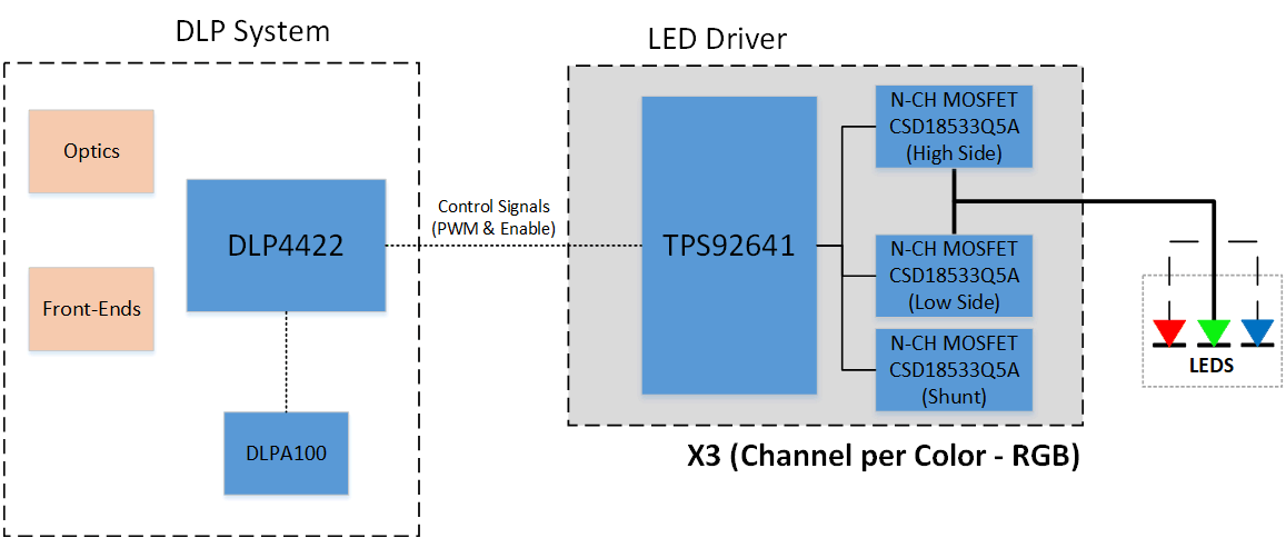
Section 1.2 shows the LED Driver and the 3 independently controller channels, one for each color. Each channel has been configured and designed with existing series LEDS that operated at different voltage & current levels.

Table 2 describes the max LED voltage and current levels that this board is configured to support.

Table 2. LED Operating Specs

COLOR CURRENT (A) VOLTAGE (V)
RED 8 14.2
GREEN 10 15.8
BLUE 10 15.8