JAJU808 July 2021
- 概要
- リソース
- 特長
- アプリケーション
- 5
- 1System Description
-
2System Overview
- 2.1 Block Diagram
- 2.2
Design Considerations
- 2.2.1 System Control and Processing
- 2.2.2 Analog Front End
- 2.2.3 Input Voltage Monitoring: 5 V, 20 V, 40 V, and ±5 V
- 2.2.4 Bidirectional Current Sense: ±2 A
- 2.2.5 Unipolar Current Sense: 0.25 A to 1 A
- 2.2.6 TMP461-SP: Local and Remote Temperature Sensing
- 2.2.7 NTC Thermistor Temperature Sensing
- 2.2.8 Adjustable Voltage Source
- 2.2.9 Fixed Output Current Source
- 2.2.10 Adjustable 4-mA Current Source
- 2.2.11 Power Tree and Power Sequencing
- 2.3 Highlighted Products
- 3Hardware, Software, Testing Requirements, and Test Results
- 4Design and Documentation Support
- 5About the Author
3.2.2 Current Monitor Test Setup
 Figure 3-3 Current Monitor Test
Setup
Figure 3-3 Current Monitor Test
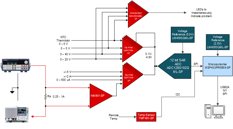
SetupTo test the current monitoring circuits, a power supply and electronic load are required. The power supply provides a voltage on one side of the sense resistor, and the other side of the sense resistor is connected to the electronic load. For the ±2 A and 0.25–1 A monitoring, two tests are performed for each rail. All tests were done at an ambient temperature of 25°C.
The following list provides the test procedure for Noise floor:
- Short both sides of the sense resistor to ground.
- Open Code Composer Studio (CCS) to run the MSP430 software.
- Configure the MSP430 software for either internal or external ADC, and set the desired ADC channel.
- Capture and plot 1000 plots by using memory export and Microsoft Excel to convert the digital data to the ADC voltage reading using the ADC conversion equation.
- Calculate the actual current
reading by solving the linear equation Equation 8.
- Repeat for the rest of the other current inputs.
The following list provides the test procedure for Linearity
- Connect the power supply to the desired terminal block as shown in Figure 3-3.
- Open CCS to run the MSP430 software.
- Configure the MSP430 software for either internal or external ADC, and set the desired ADC channel.
- Capture and export 1000 measurements by using the memory export and Microsoft Excel to convert the digital data to the voltage reading using the ADC conversion equation.
- Calculate the actual current
reading by solving the linear equation: Equation 9.
- Repeat over the rest of the current range.