JAJU835 December 2021
- 概要
- リソース
- 特長
- アプリケーション
- 5
- 1System Description
-
2System Overview
- 2.1 Block Diagram
- 2.2 Highlighted Products
- 2.3
Design Considerations
- 2.3.1
Design Hardware Implementation
- 2.3.1.1 Hall-Effect Switches
- 2.3.1.2 Linear Hall-Effect Sensor Output
- 2.3.1.3 Power Supply
- 2.3.1.4 Transistor Circuit for Creating High-Voltage Enable Signal
- 2.3.2 Alternative Implementations
- 2.3.1
Design Hardware Implementation
- 3Hardware, Software, Testing Requirements, and Test Results
- 4Design and Documentation Support
2.3.1.1.3 U3 and U4 Tamper Sensor Configuration
Switches U3 and U4 are the optional tamper sensors. To disable switch U3, depopulate resistor R20 and place a 0-Ω resistor between pads 1 and 2 of the R18 3-pad footprint. Switch U4 can also be disabled by depopulating resistor R19 and placing a 0-Ω resistor between pads 1 and 2 of the R17 3-pad footprint. U3 and U4 have their GND pins connected to the GND of the board instead of an output of a Hall sensor, so they are always powered as long as resistors R19 and R20 are populated. Both of these devices use the DRV5032FA SOT-23 package and respond to both positive and negative magnetic flux density readings. The output of these devices is assured to be asserted low when the absolute value of the sensed magnetic flux density is greater than 4.8 mT and asserted high when the absolute value of the sensed magnetic flux density is less than 0.5 mT.
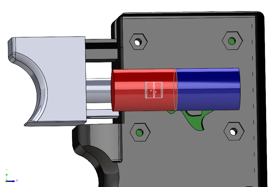
Switches U3 and U4 are for making the design robust against the magnet orientation shown in Figure 2-12. In this orientation, U1 detects a strong positive field and U2 detects a strong negative field, thereby triggering the wake-up sensor and stray field sensor. Switches U3 and U4 can detect the strong magnetic field from this orientation and put the system in sleep mode. These switches are spread out from each other to cover a wider sensing range. U3 and U4 are also placed so that the sensed magnetic flux density from the trigger magnet is small enough to not be misinterpreted as an external magnetic field.
 Figure 2-12 Additional Magnet Orientation
Detected by Tamper Hall Sensors