JAJU837 March 2022
2.3.4 Sensor Location
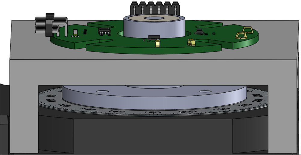
Simulations of the magnetic field were performed to evaluate the potential locations for on-axis, in-plane, and off-axis alignments.
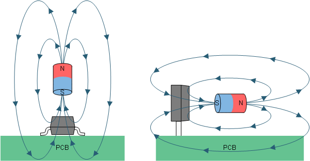
With a diametric magnet, the largest magnitude magnetic field vector at any air gap distance occurs when evaluating the field aligned to the polarization of the magnet. In this case, the first target location to examine is centered vertically with the magnet along a line directed radially outward from the center of the magnet.
 Figure 2-4 In-Plane Sensor Alignment
At this location, it is worthwhile to examine the peak magnetic flux density as well as the quality of the magnetic field for each component of the B-field over one full rotation. Figure 2-5 demonstrates the peak magnitude which is observed as the horizontal distance of the sensor changes as depicted in Figure 2-4.
The subsequent plots depict the magnetic field vector components at a few select locations to demonstrate the nature of the magnetic field. In each case the sensor location is perfectly aligned with the center of the magnet, and therefore there is no Z component in the vector.
2-mm Airgap Magnetic Field Inputs is an example of a sensor placed too close to the magnet source. The input on the (X-axis) has a peak value of nearly 150 mT while the (Y-axis) input has a peak value over 300 mT, which exceeds the linear input range for TMAG5170.
Additionally, there is some minor harmonic distortion to the sinusoidal inputs. Ultimately any distortion to the magnetic field inputs results in some periodic angle error. For all magnets, the sinusoidal nature typically improves with range.
5.9-mm Airgap Magnetic Field Inputs shows a case where the field is too far from the sensor. While the X and Y components have an ideal sinusoidal form, the 4.5 mT peak input signal is too small to be used in high-precision applications. With such a small input signal, the output noise could cause significant errors in angle calculations.
The goal is to target an input near to the maximum of the linear magnetic sensing range of the target sensor. With target devices such as TMAG5170 and DRV5055, it is necessary to allow for system tolerances while selecting a sensor location to maximize SNR. Variations in device sensitivity, installation alignment, and magnet quality can all have an impact on the observed field magnitude.
Sensitivity options for these two devices are shown in Table 2-1.
| DEVICE | LINEAR MAGNETIC SENSING RANGE (BL) |
|---|---|
| TMAG5170A1 | ±25 mT , ±50 mT, ±100 mT |
| TMAG5170A2 | ±75 mT , ±150 mT, ±300 mT |
| DRV5055A1 DRV5055Z1 | ±22 mT |
| DRV5055A2, DRV5055Z2 | ±44mT |
| DRV5055A3, DRV5055Z3 | ±88 mT |
| DRV5055A4, DRV5055Z4 | ±176 mT |
To allow for either device, a horizontal sensor range of 4.65 mm (DRV5055) and 5.9 mm (TMAG5170) from the magnet face were selected to ensure at all possible positions that the input field would be within the BL of the TMAG5170A1 using the ±100 mT setting and DRV5055A4.
At this range, the expected input magnetic field components are shown in 5.9-mm Airgap Magnetic Field Inputs.
It is evident that the sensor inputs at this range are appropriate for TMAG5170, but there is significant amplitude mismatch between the X and Y axes. If these inputs were used directly, the resulting angle calculation would effectively map an elliptical input. The arctangent is a circular function, and so this contributes significant measurement error if not corrected. Mapping the X and Y magnitudes into a coordinate plane reveals this relationship.
The effective angle error is significant. To counter this effect, attenuate the (X-axis) results or the (Y-axis) result requires a gain increase. Either transformation results in normalization of the inputs for the angle calculation and resolves this error to the expected circular format.
5.9-mm Airgap Magnetic Field Inputs shows that the in-plane alignment is not ideal for DRV5055 in the SOT-23 package option due to the directionality of the magnetic field vector. When perfectly coplanar to the center of the rotating magnet, there is no vertical component. If using the SOT-23 package option for this device, the sensor detects the Z-component of the field vector which in this alignment is 0 mT for all angles. Instead, it is more ideal to use the LPG through-hole package in this location. TIDA-060040 includes an optional component footprint for this package variant adjacent to the target location for the SOT-23 package. Make sure the sensors have the same vertical spacing from the PCB to ensure each observes an equivalent input from the rotating magnet, and that the sensor is installed orthogonal to the surface of the PCB. If using the DRV5055 solution, remove the unused package option to allow for a more ideal PCB layout.
 Figure 2-10 DRV5055 Sensitivity
An alternative to setting tight controls for the mechanical assembly using the TO-92 package is to provide vertical offset for the sensor location which results with a component of the magnetic field vector directed vertically.
 Figure 2-11 Off-Axis Sensor Alignment
The result is an alignment which is no longer coplanar to the magnet center. This placement is referred to as off-axis (or out-of-plane). In effect, all placements which are not coplanar to the magnet or centered on the axis of rotation fall into this category. The key characteristic is that the magnetic field vector has a sinusoidal component in all three axes. As a result, there is a wide range of locations suitable for the SOT-23 package option.
Off-Axis Sensor Alignment shows a sensor location where the only change from the in-plane sensor alignment is a vertical offset of 3.175 mm. This results with the same horizontal alignment from the magnet face, and the sensor is now coplanar to the upmost face of the magnet. In this location the magnitude of each field component is shown in Off-Axis Magnetic Field Inputs.
Depending on the vertical placement, the magnitude of each field component may vary, and use of a 3D sensor allows for selection of the two axes which provide the best quality inputs.
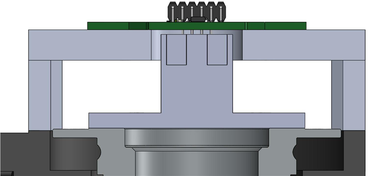
Aside from the off-axis and in-plane positions, the final alignment to examine is the on-axis placement.
 Figure 2-13 On-Axis Sensor Alignment
This is a unique location where the magnetic field vector is inherently parallel to the circular face of the magnet. This condition is ideal for 3D sensors, such as TMAG5170. Since the vector is entirely within the XY plane, a single sensor should experience perfectly sinusoidal inputs when monitoring these axes.
On-Axis Magnetic Field Inputs shows the sensor inputs at a range of 3 mm above the magnet.