JAJU873 August 2020
- 概要
- リソース
- 特長
- アプリケーション
- 5
- 1 System Description
- 2System Overview
- 3Hardware, Software, Testing Requirements, and Test Results
- 4Design and Documentation Support
- 5About the Author
3.2.1 Hardware Configuration
PCB Overview
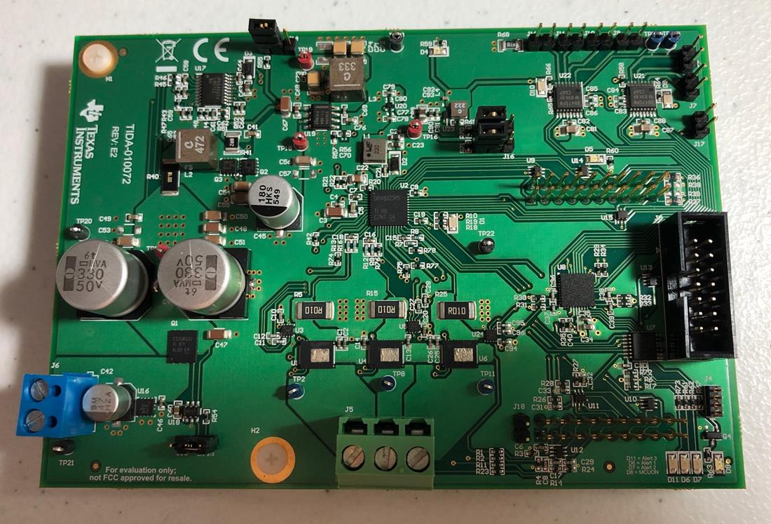
Figure 3-1 and Figure 3-2 show the top and bottom views of the TIDA-010072 with the LAUNCHXL-F28027F Launchpad (LP) connected. The top side of the LP is shown in Figure 3-3.
 Figure 3-1 TIDA-010072 Top
 Figure 3-2 TIDA-010072 Bottom
 Figure 3-3 Launchpad Top
LaunchPad Configuration
The C2000 LaunchPad has two separate power domains for the purpose of allowing JTAG isolation. Jumpers JP1, JP2, and JP3 configure whether the USB power is passed to the target device.
When using the LAUNCHXL-F28027F, the following configuration of the LP board is necessary. The jumper and switch settings are outlined in Table 3-2. Jumpers JP1, JP2, and JP3 are disconnected because the target device will be powered from the TIDA-010072 power supply.
|
CONNECTOR |
CONNECTION |
DESCRIPTION |
|---|---|---|
|
JP1 |
Disconnected |
Enable 3.3 V to target device |
|
JP2 |
Disconnected |
Enable GND to target device |
|
JP3 |
Disconnected |
Enable 5.0 V to target device |
| S3 | OFF | Disconnect the Piccolo serial pins from the XDS100 UART |
| S1 | OFF-ON-ON | bootROM configuration |
For more details, please refer to the LAUNCHXL-F28027 C2000 Piccolo LaunchPad Experimenter Kit User’s Guide.
TIDA-010072 Configuration
|
CONNECTOR |
CONNECTION |
DESCRIPTION |
|---|---|---|
|
J1 |
LP |
Launchpad connector |
|
J2 |
LP |
Launchpad connector |
|
J3 |
MSP-FET JTAG |
Required for valve control and TMP1075 readout |
|
J4 |
Optional |
MSP430FR2155 serial connector |
|
J5 |
Motor |
3-P BLDC Motor connector |
|
J6 |
Power Input |
DC Power Supply Input connector |
|
J7 |
Bidirectional Valve |
U21 DRV8847 OUT1 & OUT2 connector |
|
J8 |
Bidirectional Valve |
U21 DRV8847 OUT3 & OUT4 connector |
|
J9 |
Unidirectional Valve |
U22 DRV8847 OUT1 connector |
|
J10 |
Unidirectional Valve |
U22 DRV8847 OUT2 connector |
|
J11 |
Unidirectional Valve |
U22 DRV8847 OUT3 connector |
|
J12 |
Unidirectional Valve |
U22 DRV8847 OUT4 connector |
|
J13 |
Pin 2-3 |
Enable LM74700 Ideal Diode Controller |
|
J14 |
Pin 2-3 |
Enable LMR33630 12V Boost |
|
J15 |
Pin 2-3 |
Enable TPS62840 3.3V Buck |
|
J16 |
Pin 2-3 |
Enable TPS7A0233 3.3V LDO |
|
J17 |
Optional |
I2C connector for debugging DRV8847 |
|
J18 |
Optional |
I2C connector for debugging TMP1075 |
System Hardware Test Setup
 Figure 3-4 HW Setup for Blower
Tests
Figure 3-4 HW Setup for Blower
TestsThe HW setup for blower tests is shown in Figure 3-4. The test equipment used for the TIDA-010072 test session is shown in Table 3-4.
| EQUIPMENT | PART NUMBER |
|---|---|
| Adjustable power supply | Chroma 62006p-30-80 |
| C2000 LaunchPad | LAUNCHXL-F28027F |
| Oscilloscope | Teledyne LeCroy WaveSurfer 24Xs |
| Laptop | HP Elitebook 830 G6 |
| MSP MCU Programmer and Debugger | MSP-FET |
| 24-V Single Pole Pair BLDC | Wonsmart WS7040-24-V200 |
| 24-V Single Pole Pair BLDC | Boreasa C65MS1-L5 |
| 12-V Solenoid Valve, Unidirectional Operation | Makeblock 59001 |
| 12-V Solenoid Valve, Bidirectional Operation | Spartan Scientific 3827-B60-AA82B |
The jumpers on the TIDA-010072 and LP boards were set as described in Table 3-3 and Table 3-2, respectively.
The boards were connected using the TIDA-010072 female headers (J1 and J2) to the LP male headers (J1, J5, J2 and J6) as shown in Figure 3-2. The LP was connected to the computer via a USB cable.
The power supply was connected to the TIDA-010072 J6 terminal connector and the BLDC motor was connected to the TIDA-010072 J5 terminal connector as shown in Figure 3-4. The Chroma power supply was set to 24V with the current limit set to 10A.
For the valve functional test, two Makeblock and one Spartan Scientific valves were connected to the TIDA-010072 male headers (J7, J11, J12) for unidirectional and bidirectional operation, respectively. To control the valves, the MSP-FET was connected to TIDA-010072 JTAG connector (J3) and the USB port of the laptop as shown in Figure 3-5. Note that this test is independent of the C2000 LP.
 Figure 3-5 HW Setup for Valve
Tests