JAJU873 August 2020
- 概要
- リソース
- 特長
- アプリケーション
- 5
- 1 System Description
- 2System Overview
- 3Hardware, Software, Testing Requirements, and Test Results
- 4Design and Documentation Support
- 5About the Author
3.3.2 Valve Test Result
The following valve tests were conducted:
- Valve Turn-On Time (Makeblock 59001)
- Valve Turn-Off Time (Makeblock 59001)
- Consecutive Valve operation (2x Makeblock 59001)
- Bidirectional Valve operation (Spartan Scientific 3827-B60-AA82B)
DRV8847 Valve Turn-On Time
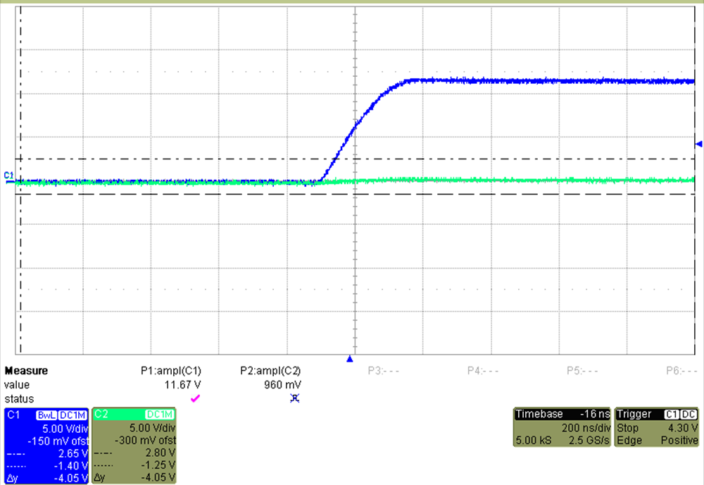
The valve turn-on transition (<400 ns) is clean with minimal overshoot as shown in channel 1 in Figure 3-19.
 Figure 3-19 DRV8847 Valve Turn-On
Time
Figure 3-19 DRV8847 Valve Turn-On
TimeDRV8847 Valve Turn-Off Time
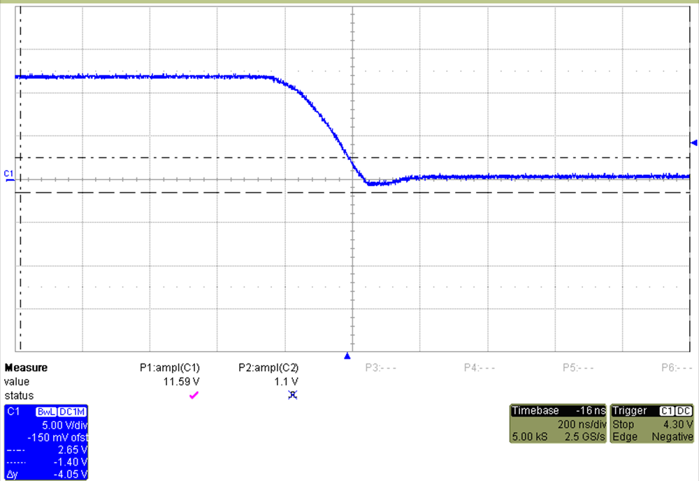
The valve turn-off transition (<400ns) is clean with minimal overshoot as shown in channel 1 in Figure 3-20.
 Figure 3-20 DRV8847 Valve Turn-Off
Time
Figure 3-20 DRV8847 Valve Turn-Off
TimeDRV8847 Consecutive Valve Operation
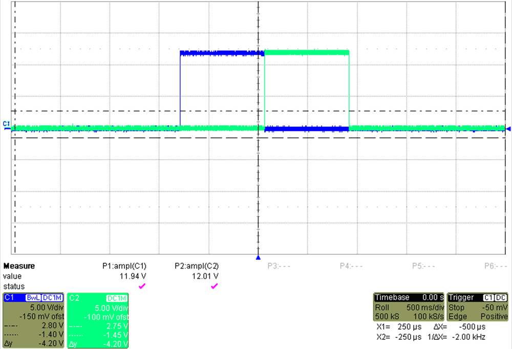
The transition between valves is clean with no overshoot as shown in channel 1 and 2 in Figure 3-21. Valve is seen and heard to engage during both events.
 Figure 3-21 DRV8847 Consecutive Valve
Operation
Figure 3-21 DRV8847 Consecutive Valve
OperationDRV8847 Bidirectional Valve Operation
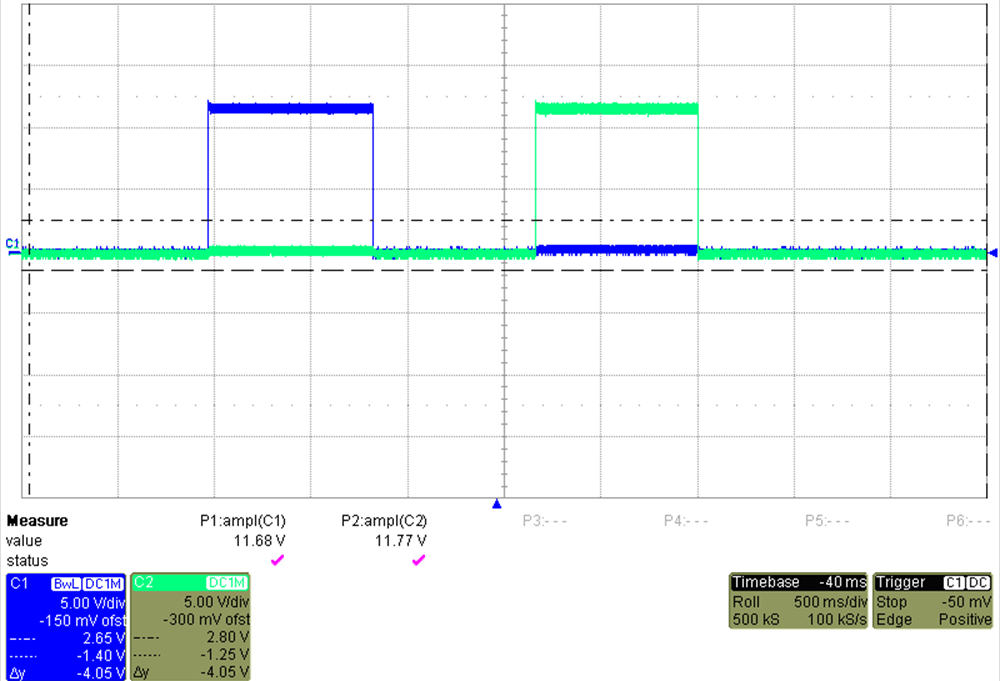
The voltage waveforms for each side matched as shown in channel 1 and 2 in Figure 3-22. The observed current draw was the same for either direction. The valve is seen and heard to engage during both events.
 Figure 3-22 DRV8847 Bidirectional Valve
Operation