JAJU873 August 2020
- 概要
- リソース
- 特長
- アプリケーション
- 5
- 1 System Description
- 2System Overview
- 3Hardware, Software, Testing Requirements, and Test Results
- 4Design and Documentation Support
- 5About the Author
3.2.2 Software Configuration
Initial setup
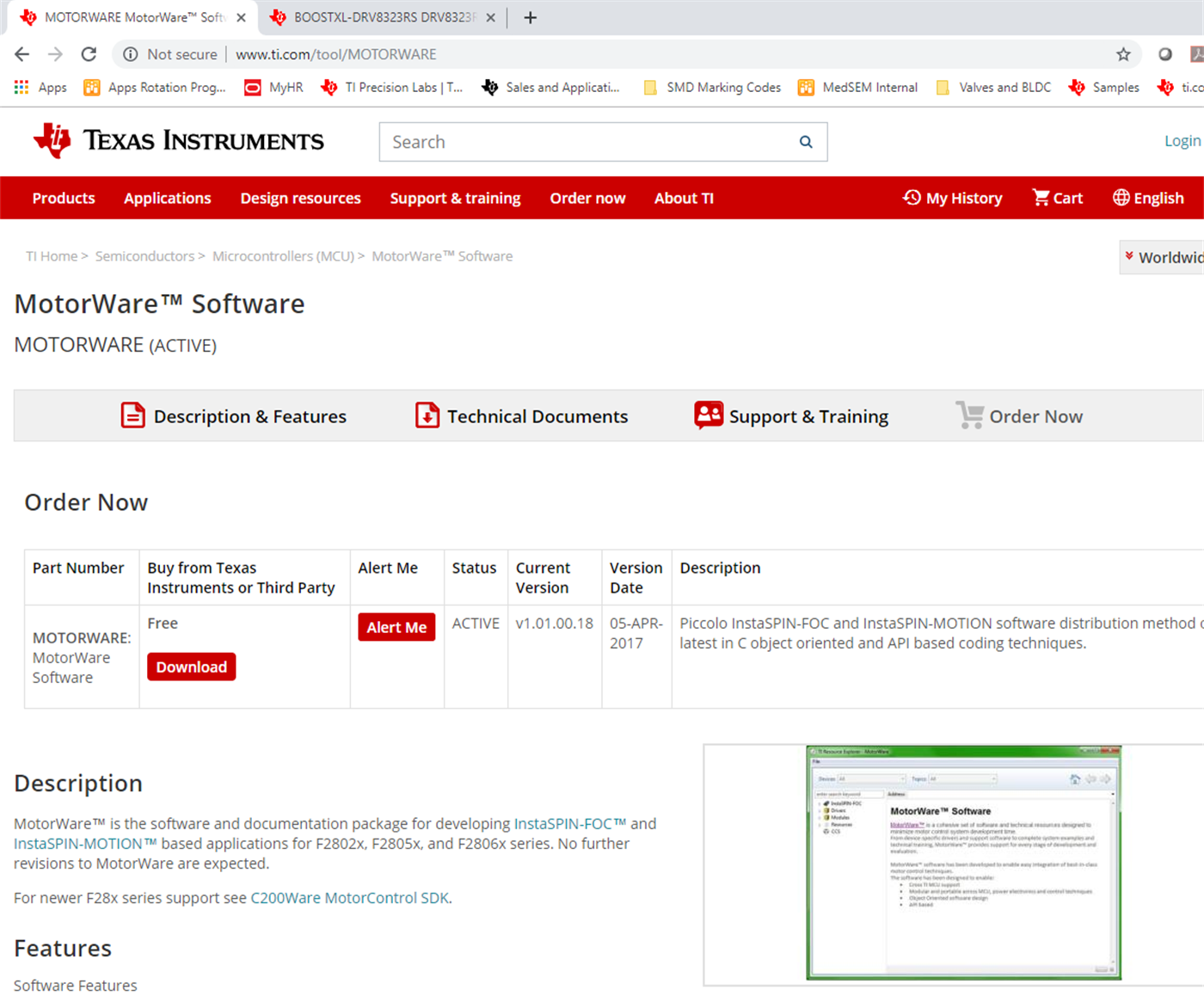
Step 1. Download Motorware 1.01.00.18 from ti.com and install in the default directory as shown in Figure 3-6 and Figure 3-7.
 Figure 3-6 Download Motorware
 Figure 3-7 Install in the default
directory
Figure 3-7 Install in the default
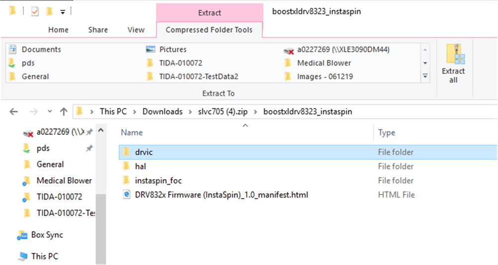
directoryStep 2. Download DRV832x Firmware (InstaSpin) from ti.com.
Step 3. Copy the downloaded DRV832x FW folders (drvic, hal and instaspin_foc) to the corresponding motorware_1_01_00_18 directory (C:\ti\motorware\motorware_1_01_00_18) as shown in Figure 3-8 and Figure 3-9. The specific target locations are shown here:
- C:\ti\motorware\motorware_1_01_00_18\sw\drivers\drvic
- C:\ti\motorware\motorware_1_01_00_18\sw\modules\hal
- C:\ti\motorware\motorware_1_01_00_18\sw\solutions\instaspin_foc
 Figure 3-8 Copy the downloaded DRV832x FW
folders
  Figure 3-9 Target locations
 Porting lab05h for DRV8323
Unfortunately, the default DRV8323 FW download doesn’t include Proj_lab05h (at the writing of this design guide). In order to use the lab05h project with the DRV8323 device, a pre-existing DRV8353 lab05h from the motorware solution folder was ported. The template project under located in this directory:
- C:\ti\motorware\motorware_1_01_00_18\sw\solutions\instaspin_foc\boards\drv8353rx_evm_revA\f28x\f2802xF\projects\ccs
Note, when copying a CCS template project from one directory to another, do not copy the .launches and .settings folders. This will cause errors when debugging the newly ported project. CCS will auto generate the appropriate .launches and .settings folders.
Once the lab05h project is copied from the template DRV8353 to the target DRV8323 solutions directory, import the project to CCS to begin the porting process. The following items require minor modifications to support DRV8323 instead of DRV8353:
- proj_lab05h.c (locate instances of DRV8353 and change to DRV8323 as necessary)
- .project, .cproject, .ccsproject project files (locate instances of DRV8353 and change as necessary)
- Project settings: Linked resources (locate instances of DRV8353 and change as necessary)
- Project settings: Build->C2000 Compiler->Include Options (locate instances of DRV8353 and change as necessary)
After making the changes, be sure to delete the old DRV8353 links under CCS project explorer to ensure proper compilation.
Import the CCS Projects
Step 1: Project->Import CCS Projects
Step 2: Browse for:
- C:\ti\motorware\motorware_1_01_00_18\sw\solutions\instaspin_foc\boards\boostxldrv8323_revA\f28x\f2802xF\projects\ccs
Step 3: Import Proj_lab02c and Proj_lab05h to local working directory as shown in Figure 3-10.
 Figure 3-10 Import project
 This design guide uses the following examples:
- Proj_lab02c (for identifying the motor parameters)
- Proj_lab05h (for motor step response)
When running these examples, reference the document InstaSPIN Projects and Labs User’s Guide located in the document folder of MotorWare (motorware_1_01_00_xx\docs\labs).
CCS User Interface
Each project has a specific .js scripting file located in the project. The first time running each lab, the user needs to copy the scripting file content to scripting console as shown in Figure 3-11. This will populate the CCS Expressions tab, which will enable the user to have specific controls during debug session.
 Figure 3-11 Copy the scripting file to
scripting console
Figure 3-11 Copy the scripting file to
scripting consoleFor more details on the user interface in CCS, see the InstaSPIN Projects and Labs User’s Guide in the MotorWare installation folder.
Identifying the Motor
For source code of the software, download MotorWare and go through proj_lab02c. This lab is built to identify PMSM motors with low inductance. After this lab, the motor parameters are in the following configuration: Rs, Lq, Ld, and Rated Flux. For more details on the values, see the InstaSPIN-FOC™ and InstaSPIN-MOTION™ User's Guide.
The complete instructions to use proj_lab02c is in the InstaSPIN Projects and Labs User’s Guide located in the document folder of MotorWare (motorware_1_01_00_xx\docs\labs).
The first time running each lab, the user needs to copy the scripting file content to scripting console.
To identify the motor (e.g. Wonsmart motor), the following initial settings were used in user.h:
#define Wonsmart_WS7040_24_V200     111
#define USER_MOTOR Wonsmart_WS7040_24_V200

#elif (USER_MOTOR == Wonsmart_WS7040_24_V200)
#define USER_MOTOR_TYPE                 MOTOR_Type_Pm
#define USER_MOTOR_NUM_POLE_PAIRS       (1)
#define USER_MOTOR_Rr                   (NULL)
#define USER_MOTOR_Rs                   (NULL)
#define USER_MOTOR_Ls_d                 (NULL)
#define USER_MOTOR_Ls_q                 (NULL)
#define USER_MOTOR_RATED_FLUX           (NULL)
#define USER_MOTOR_MAGNETIZING_CURRENT  (NULL)
#define USER_MOTOR_RES_EST_CURRENT      (1.0)
#define USER_MOTOR_IND_EST_CURRENT      (-1.0)
#define USER_MOTOR_MAX_CURRENT          (7.5)
#define USER_MOTOR_FLUX_EST_FREQ_Hz     (40.0)
Note that the USER_MOTOR_MAX_CURRENT parameter limits the peak current of the motor and thus determines the maximum motor acceleration/deceleration rate.
With this definition in the user.h file, the motor can be identified with running proj_lab02c. In CCS debug mode, use the Expressions tab to enable the system and run the motor identification routine as shown in Figure 3-12.
Make sure to have Continuous Refresh checked.
 Figure 3-12 Identifying motor test
After the identification routine is done, save these newly identified motor parameters to the user.h for future tests:
#define USER_MOTOR_Rs (0.103635125)
#define USER_MOTOR_Ls_d (3.24286011e-05)
#define USER_MOTOR_Ls_q (3.24286011e-05)
#define USER_MOTOR_RATED_FLUX (0.00302618463)To generate the step responses, use the lab proj_lab05h. To use this lab, see the lab instructions located in the file instaspin_labs.pdf. This file can be found under the documentation folder when installing MotorWare.
Generating these step responses will give the user the option to test the PI controller of the system. When generating the step response, the actual load used for the system must be connected to the motor. This will generate the most accurate data when running the motor. Having this lab enables the user to adjust the control according to the system performance.
The first time running each lab, the user needs to copy the scripting file content to scripting console.
To import the graph during debug session, go to Tools->Graphs->Dual Time->Import as shown in Figure 3-13. Find proj_lab05h.graphProp config file located here:
- C:\ti\motorware\motorware_1_01_00_18\sw\solutions\instaspin_foc\src
 Figure 3-13 Importing the graph
Run debug session.
Check the continuous refresh setting for both the Expressions and Graph tabs as shown in Figure 3-14.
 Figure 3-14 Measuring step response in CCS
Due to the high acceleration required for the step response test (150 kRPM/s), USER_MOTOR_NUM_POLE_PAIRS #define in user.h was changed from 1 to 2 as a workaround to the 127.0 (Q-Value(24)) max acceleration limit (gMotorVars.MaxAccel_krpmps parameter in the CCS Expressions tab).
The following settings were used for the 10 kRPM to 40 kRPM speed response test. Since the USER_MOTOR_NUM_POLE_PAIRS was redefined to 2. The real speed will be doubled of these reference spdRef settings in CCS.
These are the user control parameters used in the Expressions tab during the debug session.
- gGraphVars
- Buffer_tick unsigned long 50 // this scales the time capture window
- Buffer_mode unsigned long 2 // 1 is for current step and 2 is for speed step
-
gStepVars
- StepResponse 1 // enter 1 to start the step response test
- spdRef_Default 5 (Q-Value(24)) //initial reference speed of 10kRPM
- spdRef_StepSize 15 (Q-Value(24)) //step size is 30kRPM to achieve a target speed of 40kRPM
-
gMotorVars.CtrlVersion
- gMotorVars.Flag_enableSys 1
- gMotorVars.Flag_Run_Identify 1
- gMotorVars.MaxAccel_krpmps 100 (Q-Value(24)) //200kRPM/s max acceleration limit
- gMotorVars.Kp_spd 12.0 (Q-Value(24))
- gMotorVars.Ki_spd 0.08 (Q-Value(24))
Valve Control and Temperature Sensing
A C program in CCS was developed for the MSP430FR2155 to test the basic functions of the DRV8847 and TMP1075 devices. The code communicates with two DRV8847S devices through I2C. One DRV8847 drives up to four unidirectional solenoid valves, the other drives up to two bidirectional solenoid valves. Each valve is switched in a sequence, including the bidirectional valves. The code also communicates with three TMP1075 devices through I2C to read the temperature.