JAJU879 November 2022
- 概要
- リソース
- 特長
- アプリケーション
- 5
- 1System Description
-
2System Overview
- 2.1 Block Diagram
- 2.2 Design Considerations
- 2.3 Highlighted Products
- 2.4 System Design Theory
- 3Hardware, Software, Testing Requirements, and Test Results
- 4Design and Documentation Support
3.3.4.2 Running the Application
Run the code by going to Run → Resume or clicking the Resume button in the tool bar. systemVars.flagEnableSystem should be set to 1 after a fixed time, meaning the offset calibration has been done. The fault flags, motorVars_M1.faultMtrUse.all, should be equal to 0.
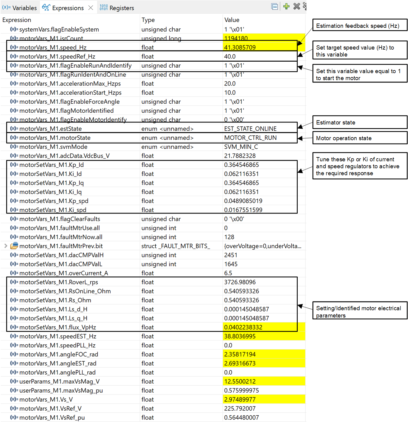
Set the variable motorVars_M1.flagEnableRunAndIdentify to 1. The motor identification will be executed; the whole process will take about 150 seconds. Once motorVars_M1.flagEnableRunAndIdentify is equal to 0 and the motor stops, the motor parameters have been identified. Copy the variable values in the Expressions window to replace the defined motor parameters in user_mtr1.h as follows:
- USER_MOTOR1_Rs_Ohm = motorSetVars_M1.Rs_Ohm's value
- USER_MOTOR1_Ls_d_H = motorSetVars_M1.Ls_d_H's value
- USER_MOTOR1_Ls_q_H = motorSetVars_M1.Ls_q_H's value
- USER_MOTOR1_RATED_FLUX_VpHz = motorSetVars_M1.flux_VpHz's value
Change MOTOR_IDENT back to 0 to disable identification after successfully indentifying the motor parameters. Rebuild and reload the application.
Once the motor parameters identification completes or are set correctly in the user_mtr1.h file, start the motor by setting motorVars_M1.flagEnableRunAndIdentify equal to 1 again. Check the following:
- Set the target speed value using the variable motorVars_M1.speedRef_Hz and watch how the motor shaft speed follows the set speed. To change the acceleration, enter a different value into the variable motorVars_M1.accelerationMax_Hzps.
- You can use the CCS Graph tool to monitor variables as described in Section 3.3.2. By default for this build level, the motor angle and current waveforms are logged.
- The default proportional gain (Kp) and integral gain (Ki) for the current controllers of the FOC system are calculated in the function setupControllers(). After setupControllers() is called, the global variables motorSetVars_M1.Kp_Id, motorSetVars_M1.Ki_Id, motorSetVars_M1.Kp_Iq, and motorSetVars_M1.Ki_Iq are initialized with the newly calculated Kp and Ki gains. Tune the Kp and Ki value of these four variables in Expressions window as shown in Figure 3-16 for the current controllers to achieve the expected current control bandwidth and response. The Kp gain creates a zero that cancels the pole of the motor’s stator and can easily be calculated. The Ki gain adjusts the bandwidth of the current controller-motor system. When a speed controlled system is needed for a certain damping, the Kp gain of the current controller will relate to the time constant of the speed controlled system.
- The default proportional gain (Kp) and integral gain (Ki) for the speed controllers of the FOC system are also calculated in the function setupControllers(). After setupControllers() is called, the global variables motorSetVars_M1.Kp_spd and motorSetVars_M1.Ki_spd are initialized with the newly calculated Kp and Ki gains. Tune the Kp and Ki value of these two variables in Expressions window as shown in Figure 3-16 for the speed controllers to achieve the expected current control bandwidth and response. Tuning the speed controller has more unknowns than when tuning a current controller. The default calculated Kp and Ki are just serve as a starting point starting point.
 Figure 3-16 Build level 4 variables in the
Expressions view