JAJU879 November 2022
- 概要
- リソース
- 特長
- アプリケーション
- 5
- 1System Description
-
2System Overview
- 2.1 Block Diagram
- 2.2 Design Considerations
- 2.3 Highlighted Products
- 2.4 System Design Theory
- 3Hardware, Software, Testing Requirements, and Test Results
- 4Design and Documentation Support
3.2.2.1 Code Composer Studio Project
To import the reference project in CCS, click Project → Import CCS Projects, and browse to <SDK install location>\solutions\tidm_02012_ecompressor\<device>\ccs and click Select Folder. Select the project called tidm_02012_ecompressor_<device> and click Finish. The project should now be visible in the Project Explorer pane in CCS.
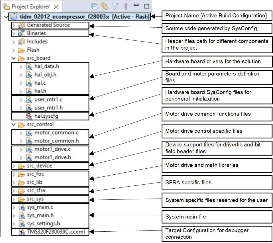
The folder src_foc includes the typical FOC modules, including transforms, PID functions, and estimators. The folder src_lib includes the InstaSPIN-FOC library and related header files. These modules are independent of the specific device and board and are used across several other solutions in the SDK.
The folder src_control includes motor drive control files that call motor control core algorithm functions within the interrupt service routines and background tasks. The folder src_sys includes some files reserved for other system features such as drivers for CAN communication. You can add your own code for system control, communication, and so forth. These modules are specific to this reference design project but are independent of the device and board.
Board-specific, motor-specific and device-specific files are in the folder src_board. These files consist of device-specific drivers to run the solution. If you want to migrate the project to your own board or other devices, you only need to make changes to the files hal.c, hal.syscfg, hal.h, and user_mtr1.h based on the pin assignments and features of your device or board.
 Figure 3-3 Project Explorer View of the
Reference Project
Figure 3-3 Project Explorer View of the
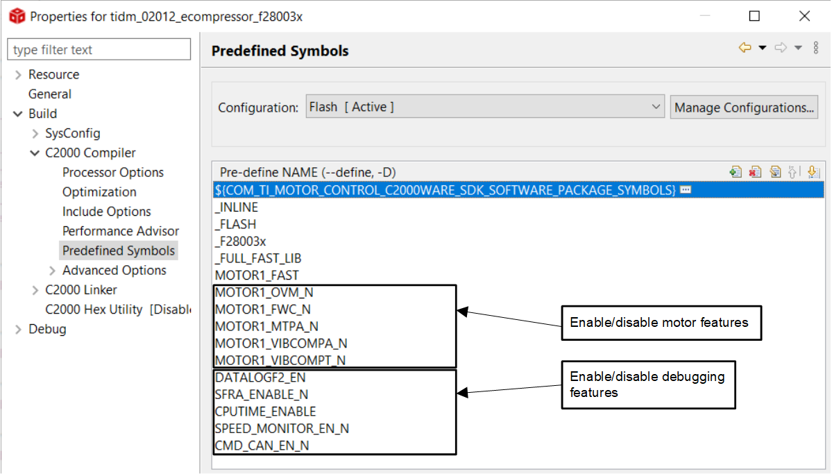
Reference ProjectThere are several optional features in the software that can be enabled and disabled using predefined symbols in the project properties. They are as follows:
- MOTOR1_OVM to enable overmodulation
- MOTOR1_FWC to enable field-weakening control (FWC)
- MOTOR1_MTPA to enable maximum torque per ampere (MTPA) mode
- MOTOR1_VIBCOMPA or MOTOR1_VIBCOMPT to enable vibration compensation
To view and edit the predefined symbols, right-click on your project and select Properties. Then go to the Predefined Symbols section of the C2000 Compiler options as shown in Figure 3-4. By default the features listed above are disabled by the "_N" appended to the symbol name. Edit the symbol to remove the "_N" to enable the feature.
 Figure 3-4 Selecting Predefined Symbols
in the Project Properties