JAJU881 December   2022


  1.   概要
  2.   リソース
  3.   特長
  4.   アプリケーション
  5.   5
  6. 1System Description
    1. 1.1 Key System Specifications
  7. 2System Overview
    1. 2.1 Block Diagram
    2. 2.2 Design Considerations
    3. 2.3 Highlighted Products
      1. 2.3.1 Devices
        1. 2.3.1.1 AWR2243
        2. 2.3.1.2 AM2732R
        3. 2.3.1.3 LP876242-Q1
        4. 2.3.1.4 LM62460-Q1
        5. 2.3.1.5 TCAN1043A-Q1
        6. 2.3.1.6 TCAN1044A-Q1
        7. 2.3.1.7 DP83TC812-Q1
        8. 2.3.1.8 TPS61379-Q1
        9. 2.3.1.9 TMP102-Q1
  8. 3System Design Theory
  9. 4Hardware, Software, Testing Requirements, and Test Results
    1. 4.1 Hardware Requirements
    2. 4.2 Test Setup
      1. 4.2.1 Virtual Antenna Array
    3. 4.3 Test Results
      1. 4.3.1 Angle Resolution Measurement
  10. 5Design and Documentation Support
    1. 5.1 Design Files
      1. 5.1.1 Schematics
      2. 5.1.2 BOM
      3. 5.1.3 PCB Layout Recommendations
        1. 5.1.3.1 20 GHz (FMCW) RF LO Sync
        2. 5.1.3.2 PCB Layer Stackup
        3. 5.1.3.3 Board Photos
    2. 5.2 Tools and Software
    3. 5.3 Documentation Support
    4. 5.4 サポート・リソース
    5. 5.5 Trademarks

Virtual Antenna Array

The two-chip cascade EVM consists of 6-TX channels and 8-RX channels as shown in Figure 4-1 giving a total number of 48 virtual channels in the MIMO virtual array. The arrangement of the channels is shown in Figure 4-2 where the MIMO array gives an aperture limited angle resolution of about 3 deg in the azimuth direction.

The antenna element design is shown in Figure 4-1.
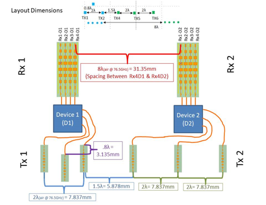
GUID-20221026-SS0I-FGLD-NH8F-TSXVBGLMX2ZJ-low.png Figure 4-1 TX and RX Channel Spacings
Figure 4-2 MIMO Virtual Array