JAJU881 December   2022


  1.   概要
  2.   リソース
  3.   特長
  4.   アプリケーション
  5.   5
  6. 1System Description
    1. 1.1 Key System Specifications
  7. 2System Overview
    1. 2.1 Block Diagram
    2. 2.2 Design Considerations
    3. 2.3 Highlighted Products
      1. 2.3.1 Devices
        1. 2.3.1.1 AWR2243
        2. 2.3.1.2 AM2732R
        3. 2.3.1.3 LP876242-Q1
        4. 2.3.1.4 LM62460-Q1
        5. 2.3.1.5 TCAN1043A-Q1
        6. 2.3.1.6 TCAN1044A-Q1
        7. 2.3.1.7 DP83TC812-Q1
        8. 2.3.1.8 TPS61379-Q1
        9. 2.3.1.9 TMP102-Q1
  8. 3System Design Theory
  9. 4Hardware, Software, Testing Requirements, and Test Results
    1. 4.1 Hardware Requirements
    2. 4.2 Test Setup
      1. 4.2.1 Virtual Antenna Array
    3. 4.3 Test Results
      1. 4.3.1 Angle Resolution Measurement
  10. 5Design and Documentation Support
    1. 5.1 Design Files
      1. 5.1.1 Schematics
      2. 5.1.2 BOM
      3. 5.1.3 PCB Layout Recommendations
        1. 5.1.3.1 20 GHz (FMCW) RF LO Sync
        2. 5.1.3.2 PCB Layer Stackup
        3. 5.1.3.3 Board Photos
    2. 5.2 Tools and Software
    3. 5.3 Documentation Support
    4. 5.4 サポート・リソース
    5. 5.5 Trademarks

PCB Layer Stackup

A normal FR4 board material results in unacceptable losses for the 77-GHz antenna included in the top two layers of this design. This design uses ceramic material from Rogers Corporation to meet the dielectric requirements. Additionally, the RO4000® LoPro® series of laminates from Rogers Corporation uses a reverse-treated foil for a smoother metal. This selection of material results in a lower variation in etched-feature dimensions. With wavelengths of less than 4 mm, these tolerances are very important. By routing the 20GHz LO clock (FM_CW) on the same layer as the antennas, only one RO4000 core is required.
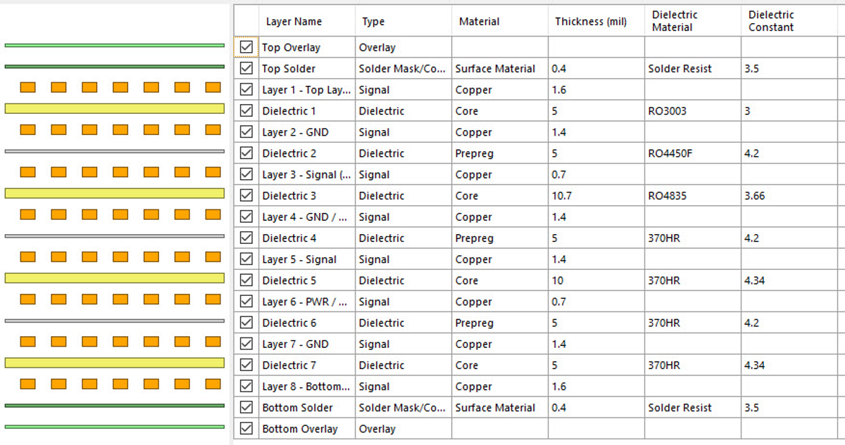
GUID-20221117-SS0I-4NKV-2Z2L-KWP6KB5KHLL8-low.png Figure 5-3 PCB Layer Stackup