SBAA549 April 2022 AMC23C11 , AMC23C12 , AMC23C14
3.2 Simulation in PSpice for TI

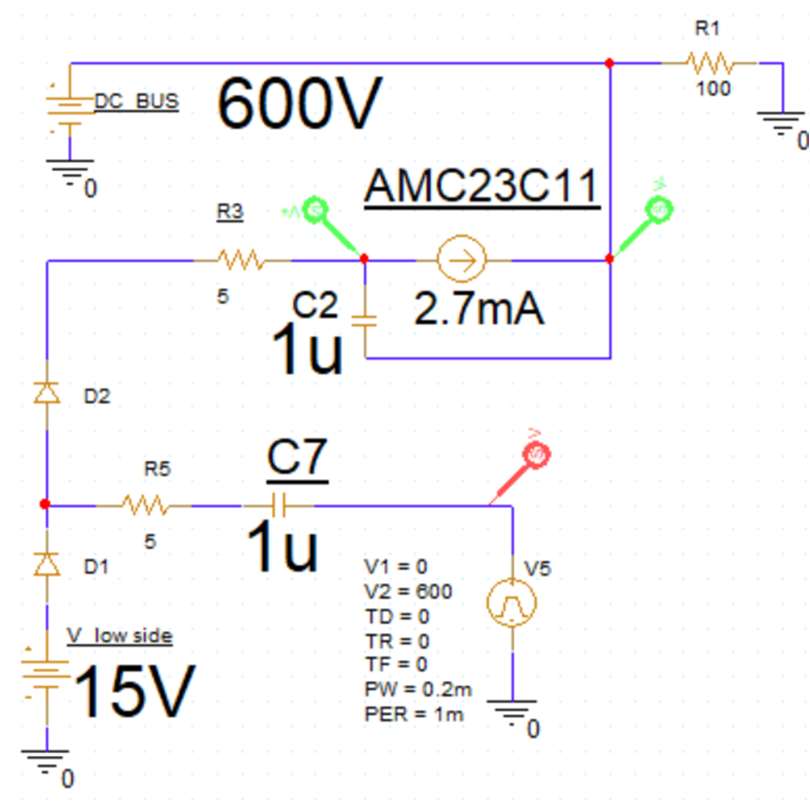
Figure 3-2 Simulation Model
The DC bus in the simulation model is 600 V, a 2.7-mA current source is used to simulate the isolated comparator, the square wave source V5 simulates the switch of the half bridge. The low-side supply is 15 V. Both capacitors, C2 and C7, are 1 μF and the current-limiting resistors R3 and R5 are 5 Ω.
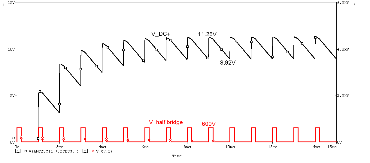
The supply voltage of the isolated comparator (V_DC+) and the half-bridge center point voltage (V_half bridge) are measured at 1-kHz switching frequency and 20% duty cycle as Figure 3-3 shows.

Figure 3-3 1 kHz, 20% Duty Cycle Power Supply
In Figure 3-3, the power supply is stabilized between 11.25 V and 8.92 V after a few PWM cycles, that is, there is a ripple of 2.33 V. Since the half-bridge circuit turns on the upper IGBT first in the first cycle, the isolated comparator is not powered until one cycle later, that is, the system is not protected from power-up short-circuit in the first cycle. An optimized solution to minimize risk is provided in Section 4.
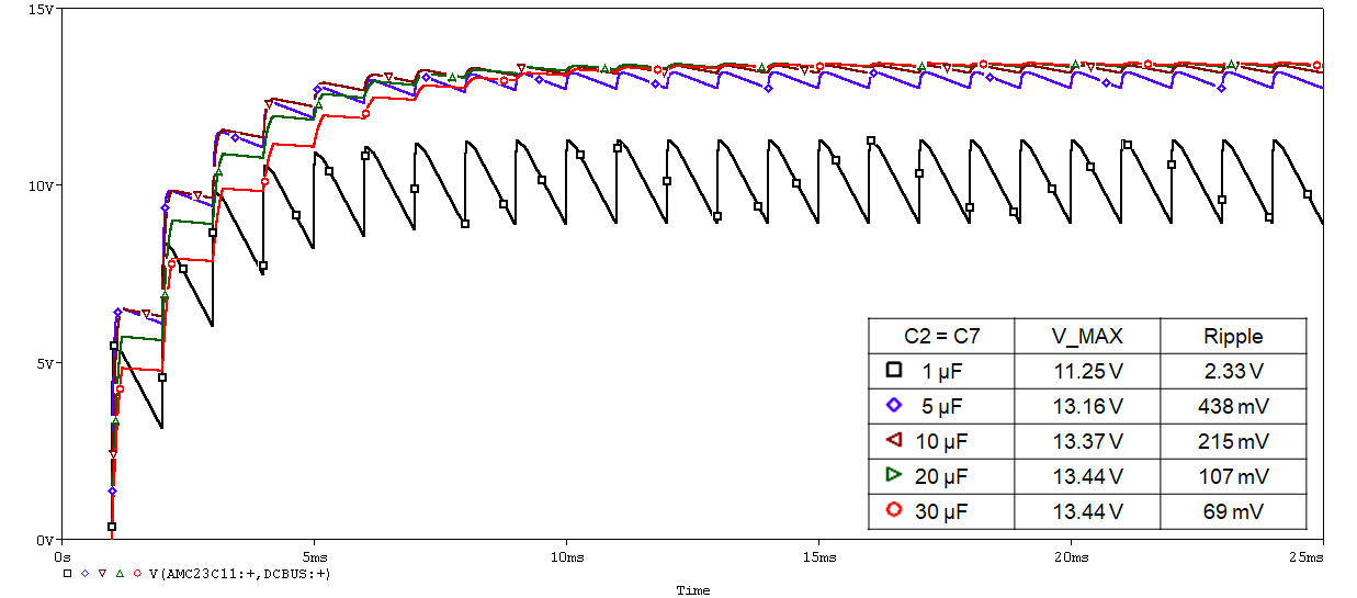
Keeping the same switching frequency and duty cycle, increase the C2 and C7 simultaneous capacitance value from 1 μF to 30 μF gradually. This method reveals that the supply voltage gradually increases and gets closer to the ideal value (13.6 V), and the power supply ripple also decreases.

Figure 3-4 Increase Capacitor Value From 1 μF to 30 μF
In Figure 3-4, V_MAX is the maximum voltage value that can be achieved with a stable supply. Therefore, controlling the capacitance of the two capacitors above 5 μF to obtain a more stable supply voltage is recommended. But a capacitance value that is too large will also increase the charging time.