SBAA587 september 2023 ADS127L21
Introduction
A digital filter is a signal processing operation used to modify the frequency content of a discrete-time signal. Digital filters are implemented in both hardware, for real-time signal processing, or in software, for post-processing at a later time. To provide the desired amplitude response, systems employ digital filters to remove unwanted frequency components. These unwanted frequency components include interference signals or signal frequencies that alias through the analog-to-digital conversion process. Additionally, digital filters shape the frequency response to meet system requirements including bandwidth, flatness, or attenuation. An additional consideration is the time delay from the filter input to output as the signal propagates mathematical operations of the filter. When applied to an analog-to-digital conversion, the filter improves the quality of the conversion data and improves the effective resolution of the system. Digital filters are commonly implemented in delta-sigma ADCs, micro-controllers, and FPGAs.
Types of Digital Filters
In general, there are three basic types of digital filters: finite impulse response (FIR) filters, infinite impulse response (IIR) filters, and sinc filters. Sinc filters are a subclass of FIR filters that have a specialized, computationally efficient implementation.
FIR filters are non-iterative filters using only sampled-input values where the impulse response output of the filter converges to a steady-state value after the input has settled within a finite number of samples. These filters can also have a linear phase that introduces constant delay across frequencies to the input signal. FIR filters are inherently stable making them appropriate for a multitude of applications. A common implementation of an FIR filter is a low-pass filter function that provides steep frequency roll-off before the Nyquist frequency to avoid signal aliasing.
 Figure 1 FIR Filter Block
Diagram
Figure 1 FIR Filter Block
DiagramIIR filters are recursive filters that depend on both the filter input values and the filter output values. When provided with unlimited mathematical resolution, the IIR filter requires an infinite amount of time for the output value to settle. IIR filters are efficient for analog-like filter implementations of arbitrary order band-pass, band-stop, high-pass and low-pass filters. IIR filters must be designed carefully since the filters can be unstable, which can result in unbounded outputs. IIR filters are sensitive to the effects of coefficient rounding and finite mathematical resolution used in the filter operation.
 Figure 2 IIR Filter Block
Diagram
Figure 2 IIR Filter Block
DiagramDigital Filters in Delta-Sigma ADCs
Digital filters are integral to the operation of a delta-sigma ADC, which rely on the concept of oversampling to improve resolution. There are two types of FIR digital filters commonly found in delta-sigma ADCs: sinc filters and wide-band filters.
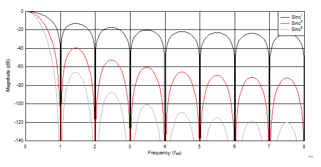
Due to size and power efficiency, sinc filters are typically used in DC signal applications where the signal changes slowly such as temperature and pressure sensors. In general, sinc filters have a sin(x)/x frequency response while offering fast settling times compared to wide-band filters. High order sinc filters are constructed by cascading sinc filters in which the filter is referred to as sincx , where x is the order of the filter. Figure 3 shows the frequency responses of various order sinc filters. The order of the filter corresponds to the number of samples required to settle the input. For example, a sinc3 filter settles in three samples.
Advantages of sinc filters include:
- Computationally efficient in terms of die area and power consumption.
- Inherently stable.
- Linear phase response
- Monotonic response with a relatively low filter latency time.
- High order implementations provide -20 dB rejection at the Nyquist frequency.
 Figure 3 Frequency Response of Sinc
Digital Filters
Figure 3 Frequency Response of Sinc
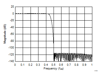
Digital FiltersWide-band filters are a class of FIR filter that multiplies the sampled input values by the filter coefficients. Wide-band filters are typically provide a flat frequency response in the pass-band and a steep transition band to reject unwanted signals at the cutoff frequency. As the name suggests, wide bandwidth filters are typically used in higher bandwidth applications such as test and measurement equipment and audio applications.Figure 4 shows the wide-band filter response of the ADS127L11. Wide bandwidth filters reduce the requirement for analog anti-aliasing filters because the filters are designed to provide attenuation at the Nyquist frequency (fs/2). In addition, wide bandwidth filters have a linear phase response, which results in consistent delay across the frequency band. However, due to the delay caused by the internal computations, the step response time is longer and is non-monotonic compared to sinc filters.
Advantages of wide bandwidth filters include:
- Flat frequency response in the pass-band, which means wide bandwidth filters do not attenuate or distort the signal power of the desired frequencies.
- Steep transition band, which simultaneously can improve the signal bandwidth while rejecting unwanted signals of the pass-band.
 Figure 4 Wide-Band Filter Frequency
Response
Figure 4 Wide-Band Filter Frequency
ResponseTo learn more about traditional digital filters in a delta-sigma ADC, see Digital Filter Types in Delta-Sigma ADCs. While digital filters in delta-sigma ADCs improve system performance through the combination of low-pass filtering and decimation, additional analog and digital filters can be required for anti-aliasing, signal conditioning, or to reject unwanted signals.
Implementing FIR & IIR Filters in FPGAs
In some applications, external FIR and IIR post-processing filters are required to provide custom filter profiles. These filters are commonly implemented in field programmable gate arrays (FPGA), digital signal processors (DSPs) and provided that an efficient number of MIPS are available, ARM core devices. Depending on the type of filter employed, there are multiple ways to implement digital filters in an FPGA. In general, use the following steps:
- Choose the type of filter and the design requirements (FIR/IIR, filter order, cutoff frequency, and so on).
- Design the filter coefficients using a software tool.
- Simulation to evaluate performance and functionality of the filter.
- Implement the filter in an FPGA using primitive elements or Hardware Description Language (HDL).
- Decide on floating-point or fixed-point arithmetic.
- Hardware-in-the-loop testing to verify performance.
The design of digital FIR and IIR filters on FPGAs can be challenging despite their efficiency and high-performance. The most difficult part of the design process is the physical implementation of the filter arithmetic on the FPGA using primitive elements or HDL coding when considering both the number of gates in the filter and the filter power consumption. This requires expertise and time from the filter designer, but the process allows for customization and control. Extensive simulation is then required to verify the performance of the filter, which can be time-consuming.
Programmable Filters in ADS127L21
There are multiple ways to implement digital filters in a system including the integrated filters within a delta-sigma ADC or custom digital filters in an FPGA. Fixed digital filters in a traditional delta-sigma ADC are sufficient for many applications, but the system can require custom filtering to meet certain non-standard requirements. Implementing digital filters in an FPGA allow for complete customization and control, but this requires a certain amount of expertise.
An ADC that offers programmable filters allows the user to implement many arbitrary filter functions within the ADC, without the penalty of extra power consumption, design time, and cost imposed required by an FPGA design. Additionally, a programmable digital filter with the ADC can replace the function of an analog filter such as a low-pass Butterworth filter. The noise, power, and PCB area of an analog filter are eliminated by implementing the analog filter function by a digital filter.
The ADS127L21 is a 24-bit delta-sigma ADC that features programmable digital filters with data rates up to 512 kSPS using the wideband filter and up to 1365 kSPS using the low-latency filter. The programmable IIR and FIR digital filters within the device allow for custom filter profiles such as high-pass filters, 50-Hz or 60-Hz notch filters, and A-weighting compensation. The ADS127L21 contains a programmable FIR filter with 128 32-bit filter taps and a programmable IIR filter with four 32-bit biquads.
Advantages of using the programmable filters in the ADS127L21 include:
- Easier Filter Implementation: After the filter coefficients are designed, the coefficients can be directly programmed to the device using SPI communication. There is no need to manually code filters using Verilog or VHDL. This can improve time to market and reduce effort required to design. The cost and power consumption of an FPGA filter are eliminated.
- Eliminate Analog Filter Blocks: Digital filters are programmable and can be modified compared to analog filters. Digital filters eliminate the noise, distortion, cost, and power consumption of an analog input filter. The filters are particularly cost effective to replace high order analog input filters.
- Flexible microcontroller (MCU) selection: Since the filters are located within the ADC, the MCU or FPGA, and are not required to implement the digital filters. As a result, this allows for a more flexible MCU selection.
- Lower Power: The digital filters inside the ADS127L21 are optimized for efficiency resulting in a lower power design than is possible with an external filter.
The ADS127L21 evaluation module (EVM) allows for plotting and testing a programmable digital filter. The process for designing a filter and evaluating the performance using the evaluation module is listed in the following steps.
- Design the filter coefficients using a software tool such as the MatLAB® Filter Designer application.
- Load the coefficients into the EVM graphical user interface (GUI) and run simulated frequency response plots.
- Test the hardware performance by applying test signals to the EVM.
For more details, see ADS127L21EVM-PDK user’s guide.
ADS127L21 Filter Examples
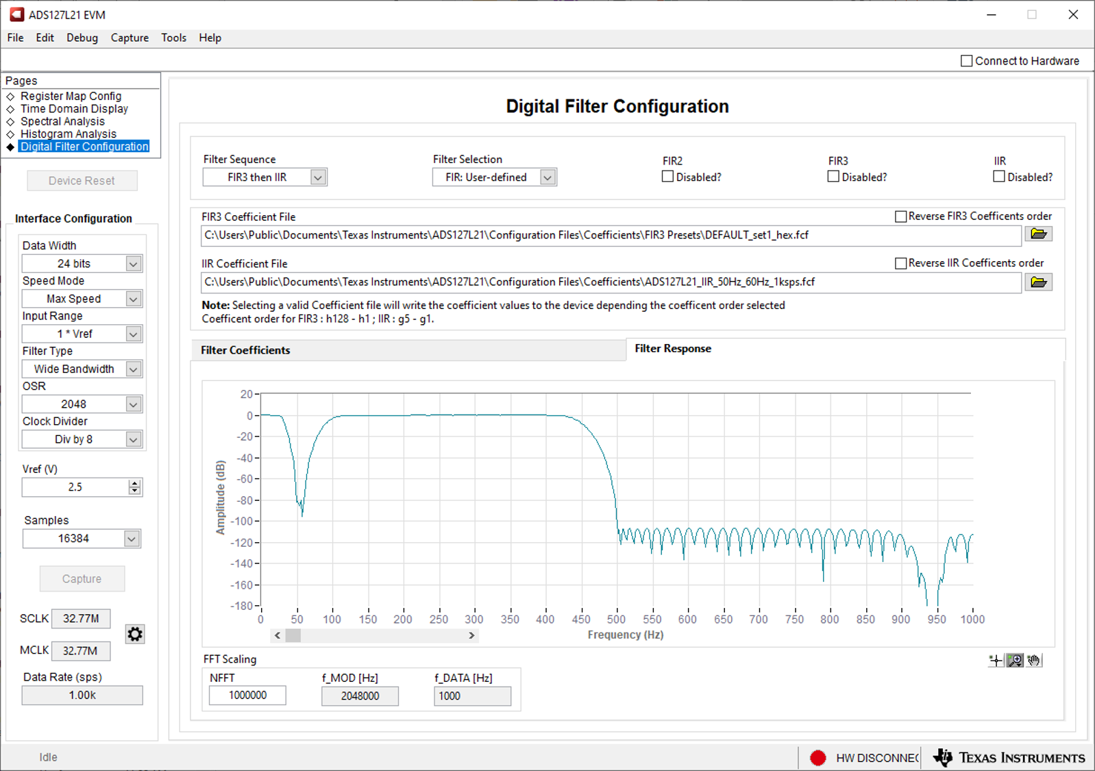
To avoid interference from the power line frequency, industrial control systems must reject 50-Hz and 60-Hz signals. Some delta-sigma ADCs, such as ADS124S08, can reject signals, but the ADC must sample at less than 20 samples per second. With the ADS127L21, a 50-Hz or 60-Hz notch filter can be implemented to achieve rejection at these frequencies while sampling at 1000 samples per second.
 Figure 5 Frequency Response of a 50 and
60-Hz Notch Filter with ADS127L21
Figure 5 Frequency Response of a 50 and
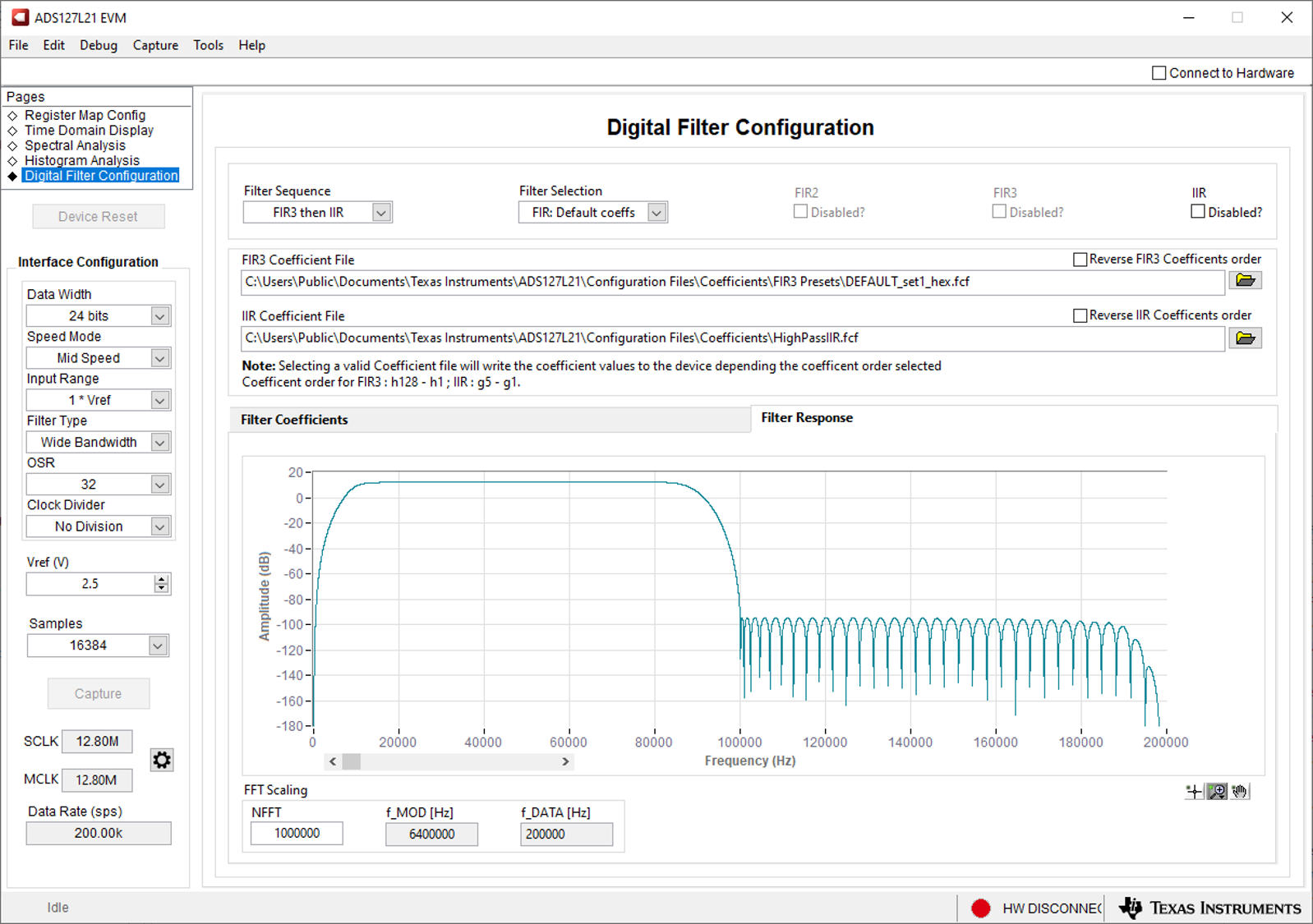
60-Hz Notch Filter with ADS127L21Applications such as vibration sensors and audio systems use AC coupling to block the DC portion of the signal from using the range intended for the AC portion of the signal. AC coupling uses a high-pass filter. The ADS127L21 programmable IIR filter digitally removes the residual DC component of the signal and low frequencies to improve resolution without requiring external filtering. Figure 6 shows an example of a 10 kHz, 8th order high-pass filter to remove signal components below 10 kHz.
 Figure 6 Frequency Response of a
High-Pass Filter with ADS127L21
Figure 6 Frequency Response of a
High-Pass Filter with ADS127L21Conclusion
Many systems use digital filters to shape the frequency response of a signal and remove noise. Delta-sigma ADCs use these filters, but they are fixed filters that do not allow user customization. FPGAs can implement high-performance and customizable digital filters, but they require a certain amount of expertise from the designer. The ADS127L21 has integrated FIR and IIR filters that the user can program directly on the chip for reduced cost and improved efficiency. This allows the user to design custom filter profiles that meet the system requirements and reduce the effort for the designer.