SBAU391A December 2021 – December 2024 TMAG5328 , TMAG5328
2 Assembly Guide
HEADON-MAG-ACC kits ordered from TI.com come pre-assembled, but in cases where the kit is printed locally, follow steps 1-4 described below.
| Item | Description | Quantity |
|---|---|---|
| Head-On Screw | Screw.STL file | 1 |
| Head-On Base | Base.STL | 1 |
| Cylinder Magnet | 1/8” diameter, ½” thickness, N52 grade, axial magnetization from K&J magnetics | 1 |
| 8333-20G |
Super Glue |
0.02 ounces |
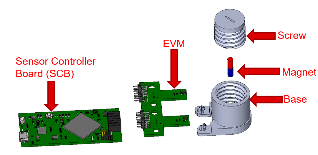 Figure 2-1 Linear Head-On Travel
Attachment Exploded View
Figure 2-1 Linear Head-On Travel
Attachment Exploded View- Identify the North and South
Pole Faces of the Cylinder Magnet
Unipolar Hall position sensors require that the appropriate magnetic pole is applied near the top of the Hall position sensor. Applying the incorrect magnetic pole to a unipolar sensor results in an output that does not respond to the magnet’s movement. As an example, if the output of a Hall switch only responds to when a south pole of a magnet is applied near the top of the package, the output will not switch if the north pole of the magnet is brought near the top of the Hall switch’s package.
For compatibility with unipolar Hall position sensors, the user must determine the north and south poles of the magnet before the magnet is placed in the screw attachment. To determine the north and south poles of the magnet, a second magnet with known north and south poles can be applied to the attachment’s magnet. If the known south pole of the second magnet is attracted to a face of the attachment magnet, that face is the north pole of the attachment magnet. In contrast, if the known south pole of the second magnet is repulsed from a face of the attachment magnet, that face is the south pole of the attachment magnet.
- Print the Screw Portion of the
Attachment (Screw.STL)
The screw contains the cavity where the magnet is eventually placed. Figure 2-2 and Figure 2-3 show the side and bottom view of the screw attachment. To use this attachment with other magnets, the diameter and length of the cavity can be altered by modifying the screw 3D print file.
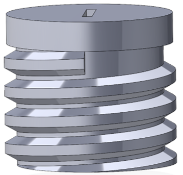 Figure 2-2 Side View of
Screw
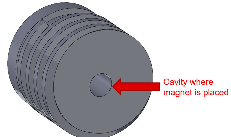 Figure 2-3 Bottom View of
Screw
 - Glue
the Magnet Into the Screw
For compatibility with south-responding unipolar Hall sensors, the south pole of the magnet must be placed above the package of the Hall sensor. This is done by inserting the north pole of the magnet, as determined from Step 1, into the cavity of the screw attachment. To ensure the magnet is secured, add glue to the north face of the magnet before inserting it into the cavity. Figure 2-4 shows the orientation of the magnet before it is inserted into the screw’s cavity.
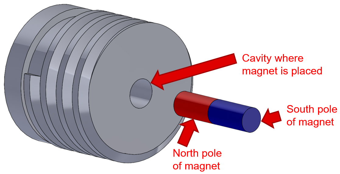 Figure 2-4 Orientation of Magnet
With Respect to Screw
Figure 2-4 Orientation of Magnet
With Respect to ScrewAfter the magnet is inserted into the cavity, push the magnet down the cavity so that only a minimum amount of the magnet sticks out of the attachment, as shown in Figure 2-5. How far the magnet is actually pushed within the cavity determines the maximum magnetic flux density reading seen in the system when the screw is fully fastened in the base (see Figure 1-2). The more the magnet is pressed within the cavity, the smaller the displacement from the actual magnet to the sensor and the smaller the maximum magnetic flux density seen in the system.
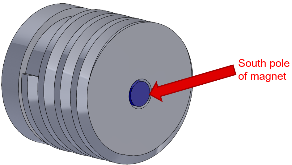 Figure 2-5 Fully-Embedded Magnet
in the Screw
Figure 2-5 Fully-Embedded Magnet
in the ScrewLeave the screw attachment unbothered until the glue fully cures after the prescribed dry time has elapsed.
- Print
the Base Portion of the Attachment (Base.STL)
The screw part of the attachment gets fastened into the top portion of the base. Figure 2-6 shows the base part of the attachment.
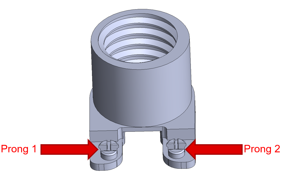 Figure 2-6 Base of
Attachment