SBAU432 December 2023 AFE7728D , AFE7768D , AFE7769D
3.2 AFE7769D Connections
- Connect the 5.5 V power supply to
power jack connector (J22) of the AFE7769D EVM.
- Check: D14 (POWER) LED should light up.
- Connect the USB Type Mini-B Cable
from PC to the USB port (J20) of the AFE7769D EVM.
- Check: D13 (USB_PWR) LED should light up.
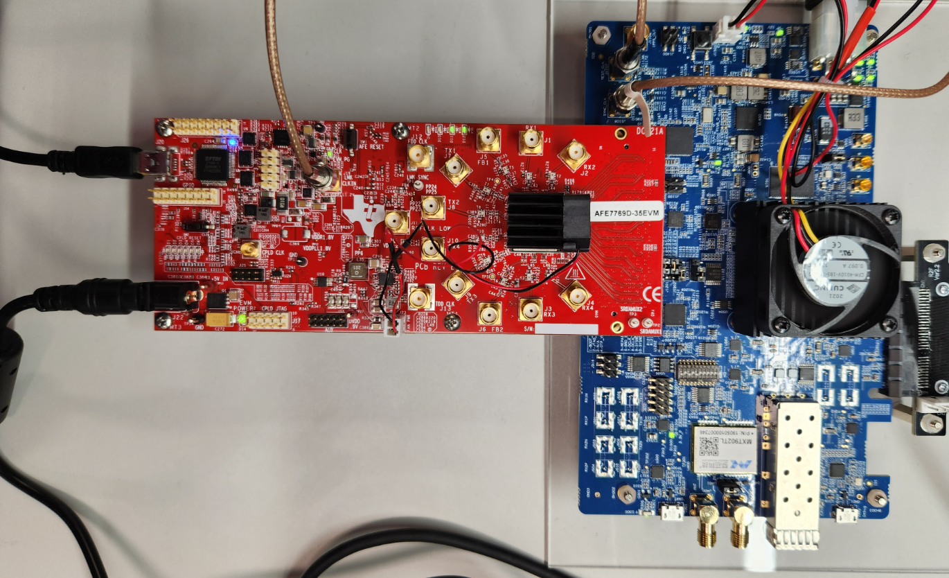
- Connect the AFE7769DEVM to the PC802 through the FMC connector.
- Connect the 122.88MHz reference
clock (SYNC_CLOCK) from the PC802 (J1106) to the LMK_CLKIN (J19) of the
AFE7769DEVM, as shown in Figure 3-2.
 Figure 3-2 Hardware Setup and
Connections AFE7769DEVM-PC802