SBAU432 December 2023 AFE7728D , AFE7768D , AFE7769D
3.5 AFE7769D Programming Method 2: Using GUI Mode
- Open the AFE77xxD GUI version
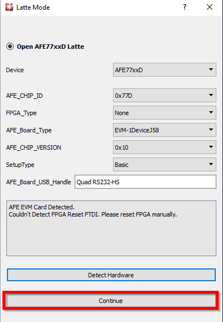
0.4. Make sure it looks like Figure 3-8, then click Continue. The “Couldn’t Detect FPGA Reset FTDI. Please reset FPGA
manually.” message is expected and can be ignored.
 Figure 3-8 Launching AFE77xxD
Latte Software
 - Wait
until the GUI loads. It will look like Figure 9. Click on “AFE77xxD-Device” tab
under the tree view on the left for the main parameters screen.
 Figure 3-9 ReadMe AFE77xxD Latte
Software
 - Click on “Browse” under “Load
System Parameters” and select the “AFE77xxD_Picocom_pc802_K1L.xlsx” config file
under “\Documents\Texas Instruments\AFE77xxDLatte\lib\configs”. After selecting
the file, click “LOAD”, and the screen should look like Figure 3-10. You should also see a message saying that the configuration was loaded in
the log window.
 Figure 3-10 Main Window: GUI
Mode
 - Set the
LMK parameters on the bottom left corner like Figure 3-11.
 Figure 3-11 Setting LMK
Parameters
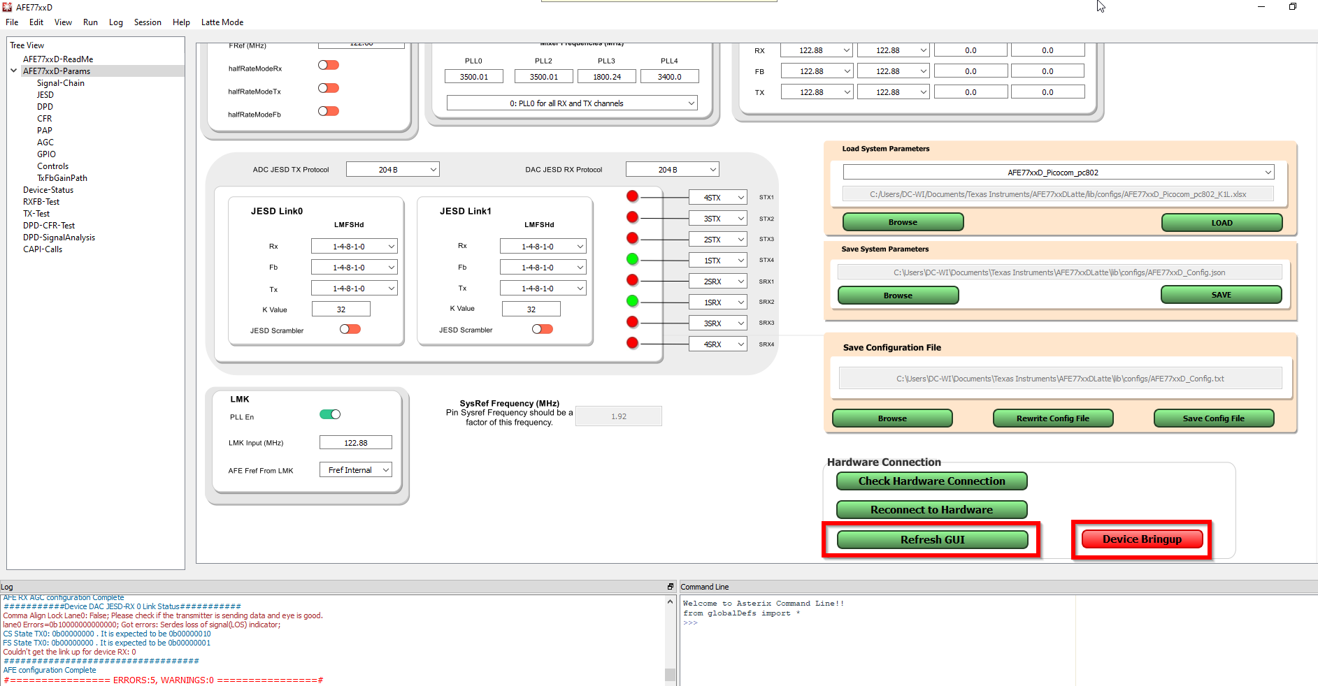
 - After that, under “Hardware
Connection”, click the refresh GUI button and you will see a message on the log
window saying “Refreshed GUI”. Then click on “Device Bringup” this will start
the bring up for the device. For proper navigation, see Figure 3-12.
 Figure 3-12 Device Bringup
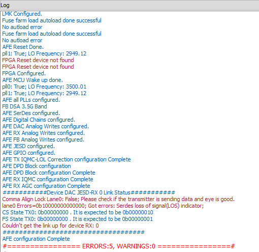
 - After
the device bringup is done, you will see some errors on the log window (shown in
Figure 3-13). Two of these errors should be “FPGA Reset device not found” and the rest
should be under the “Device DAC JESD-RX 0 Link Status” line. These errors are
expected since the JESD link is not up.
 Figure 3-13 Latte Log Qindow
Post-Bringup
 - At the top, click on Latte Mode
and navigate to Script Mode as shown in Figure 3-14.
 Figure 3-14 Switching to Script
Mode
 - Open the PC802_LMKDIV.py script
on the tree view on the left, as shown in Figure 3-15.
 Figure 3-15 PC802 LMK
Script
 - Run the
script by pressing F5 or by clicking Run > Buffer. You should see an output
in the log window like Figure 3-16, signaling the script was run with no errors. After running this script, the
LMK_LOCKED LED (D11) turns on if the 122.88 MHz reference from the PC802 is
connected.
 Figure 3-16 Running the LMK
Script
 - Click on Latte Mode and navigate
to GUI Mode as shown in Figure 3-17.
 Figure 3-17 Switching to GUI
Mode
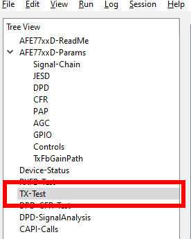
 - Click on “TX-Test” under the tree
view, as shown in Figure 3-18.
 Figure 3-18 Switching to TX-Test
Tab in Latte
 - Enable
the TDD for the TX channels by setting them to green like in Figure 3-19. Then, click “Set TX TDD”, and a message should appear on the log window that
says “TDD set”.
 Figure 3-19 Enabling TDD
Mode
 - Proceed to set up the PC802 by
following the PC802 EVB RFIC Demonstration User Guide (Version 3) (where is this doc located or what is the lit
number?) from section 2.2. Once you get to section 2.2.5, after you
enter the “start” command on the test mode tool to start sending data, type the
“AFE.adcDacSync(1)” command in the Command line in the AFE77xxD GUI. You should
now be able to see a report in the log window that the JESD link is up with no
errors like in Figure 3-20. Data will be going out of the AFE TX channel.
 Figure 3-20 JESD Link
Bringup