SBAU443 November   2023


  1.   1
  2.   Description
  3.   Get Started
  4.   Features
  5.   Applications
  6.   6
  7. 1Evaluation Module Overview
    1. 1.1 Introduction
    2. 1.2 Kit Contents
    3. 1.3 Specification
    4. 1.4 Device Information
  8. 2Hardware
    1. 2.1 System Overview
    2. 2.2 Hardware Overview
      1. 2.2.1 AC-MB Settings
        1. 2.2.1.1 Audio Serial Interface Settings
          1. 2.2.1.1.1 USB
          2. 2.2.1.1.2 18
          3. 2.2.1.1.3 Optical or Auxiliary Analog Audio Input
          4. 2.2.1.1.4 External
        2. 2.2.1.2 AC-MB Power Supply
      2. 2.2.2 PCMx140Q1EVM-PDK Hardware Settings
        1. 2.2.2.1 Line Inputs
        2. 2.2.2.2 Onboard Microphone Input
  9. 3Software
    1. 3.1 Software Overview
      1. 3.1.1 PurePath Console 3 Installation
      2. 3.1.2 PCMx140Q1EVM GUI Installation
        1. 3.1.2.1 Software Setup
    2. 3.2 Quick Start
      1. 3.2.1 Configuring the Audio Serial Bus for the I2S Output
      2. 3.2.2 32
      3. 3.2.3 Saving a Configuration
    3. 3.3 Matlab Audio Capture Example
  10. 4Hardware Design Files
    1. 4.1 PCMx140Q1EVM-PDK Schematic and Bill of Materials
      1. 4.1.1 PCMx140Q1EVM-PDK Schematic
      2. 4.1.2 PCB Layouts
      3. 4.1.3 PCMx140Q1EVM-PDK Bill of Materials
    2. 4.2 AC-MB Schematic and Bill of Materials
      1. 4.2.1 AC-MB Schematic
      2. 4.2.2 PCB Layouts
      3. 4.2.3 AC-MB Bill of Materials
  11. 5Additional Information
    1. 5.1 Trademarks
  12. 6Related Documentation

Line Inputs

For the line input configuration (shown in Figure 3-9), the PCMx140Q1 captures the audio signal provided through terminals J2 (IN1), J3 (IN2), J4 (IN3), and J5 (IN4). The input accepted in this mode is a differential, 2-VRMS, full-scale audio signal. If a single-ended source is used, the 1-VRMS signal is supported.
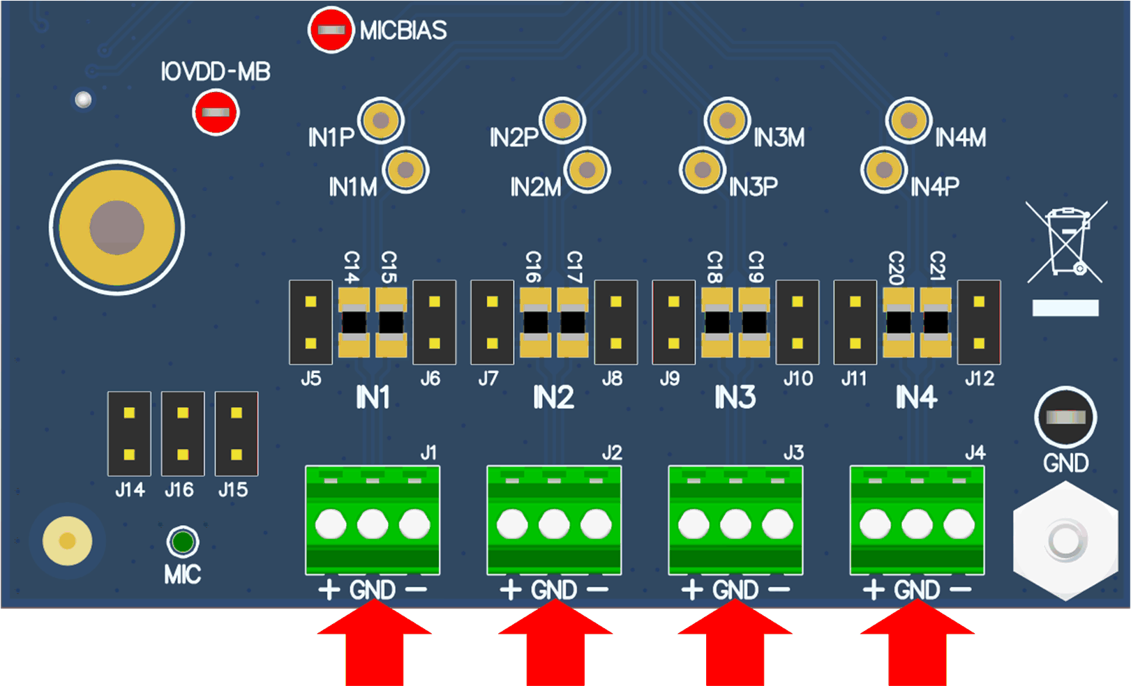
GUID-226D4F4F-846B-40AA-8D35-3566D13ECC86-low.gif Figure 2-9 PCMx140Q1EVM Connection for Line Input Application