SBAU443 November 2023
3.2 Quick Start
Configure the AC-MB for the USB audio (TDM) and the PCMx140Q1EVM for the onboard microphone input.
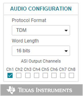
All configurations for this example are done on the audio configuration tab. In the Audio Configuration block in the lower right portion of the audio configuration tab (as shown in Figure 4-6), select a word length of 16 bits, and enable the ASI output channel 1.
 Figure 3-6 Audio Configuration
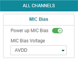
As shown in Figure 4-7, select AVDD for the MIC bias voltage and power-up the MIC bias.
 Figure 3-7 MIC Bias Configuration
The default state for the PCMx140Q1 is standby mode and, with the exception of the channel digital volume, all device configurations must be done in standby mode. The PCMx140Q1 does not provide a digital audio output in standby mode. Figure 4-8 shows how to change the mode from standby to active.
 Figure 3-8 Standby to Active Mode
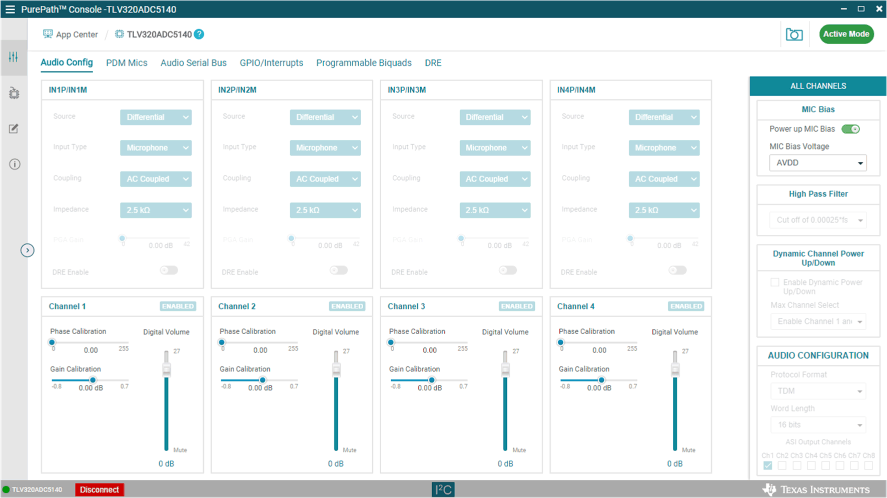
When active mode is enabled, any controls not configurable in active mode are grayed out. These controls can be changed again when the device is brought out of active mode. Figure 4-9 shows which controls are disabled.
 Figure 3-9 Disabled Controls in Active
Mode
Figure 3-9 Disabled Controls in Active
ModeAudio can now be captured on your PC using the audio program of your choice.