SBAU446 December 2023 ADC3683-SP
4.1 Evaluation Setup
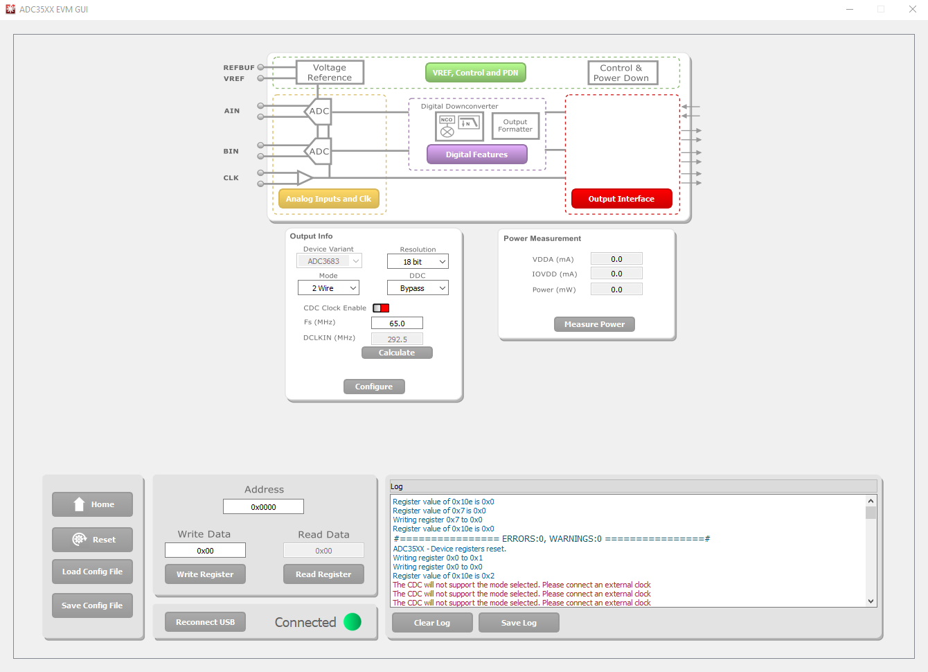
Now that the hardware is setup and the necessary software has been installed, the user can now begin to capture data. The ADC powers up into the default mode with only a few actions needed to have data ready to capture. Once the EVM is opened, check to see if the USB is connected using the indicator next to the Reconnect USB button. If the USB is not connected, then make sure the clock signal is on and click Reconnect USB. Once the USB connects, the Device Variant box auto-populates to ADC3683. Make sure the Resolution is 18 bits, the Mode is set to 2 Wire, and DDC is set to Bypass in the Output Info box. Though not necessary for configuration, input 65 for Fs and click Enter on the keyboard, followed by clicking the Calculate button in the GUI to verify the correct DCLKIN frequency. The CDC Clock Enable slider needs to be red and off, as an external clock is being supplied. Simply click the slider to turn off if the CDC Clock Enable slider is still enabled. Perform a software reset by clicking Reset and then click the Configure button to configure the part.
 Figure 4-1 ADC35XXEVM GUI Configuration
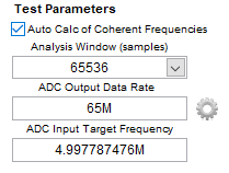
After launching HSDC Pro, a window prompts a board connection. The serial number of the TSW1400EVM appears. Click OK to connect to the TSW1400EVM. Another window pops up prompting the user to select a device. Select ADC from the Select a device drop-down menu. Click OK in the pop-up box that reads No firmware. Please select a device to load firmware into the board. Use the Select ADC drop-down menu at the top left corner to select ADC3683_2W_18bit. When prompted to update the firmware for the ADC, click Yes and wait for the firmware to download to the TSW1400EVM. Enter 65M into the ADC Output Data Rate field at the bottom left corner. Calculate the coherent 5 MHz frequency by entering 5M into the ADC Input Target Frequency box and then clicking in the Auto Calculation of Coherent Frequencies box. Enter this new coherent frequency value into the signal generator of the input signal. Click Capture to capture data from the ADC.
 Figure 4-2 HSDC Pro Frequency Configuration