SBAU452 March 2024
2.2 Board Assembly
Assembling the TMCS-A-ADAPTER EVM with the provided components and a TMCS Hall-effect isolated current sense amplifier device is necessary before using the EVM to evaluate the performance of the TMCS device. The recommended procedure for assembling the board is as follows:
- Solder the surface-mount components onto the board. This includes a TMCS device in the DVG, DVF, or DZP packages, a voltage supply bypass capacitor, a jumper resistor to ground, and (optional) surface mount test points.
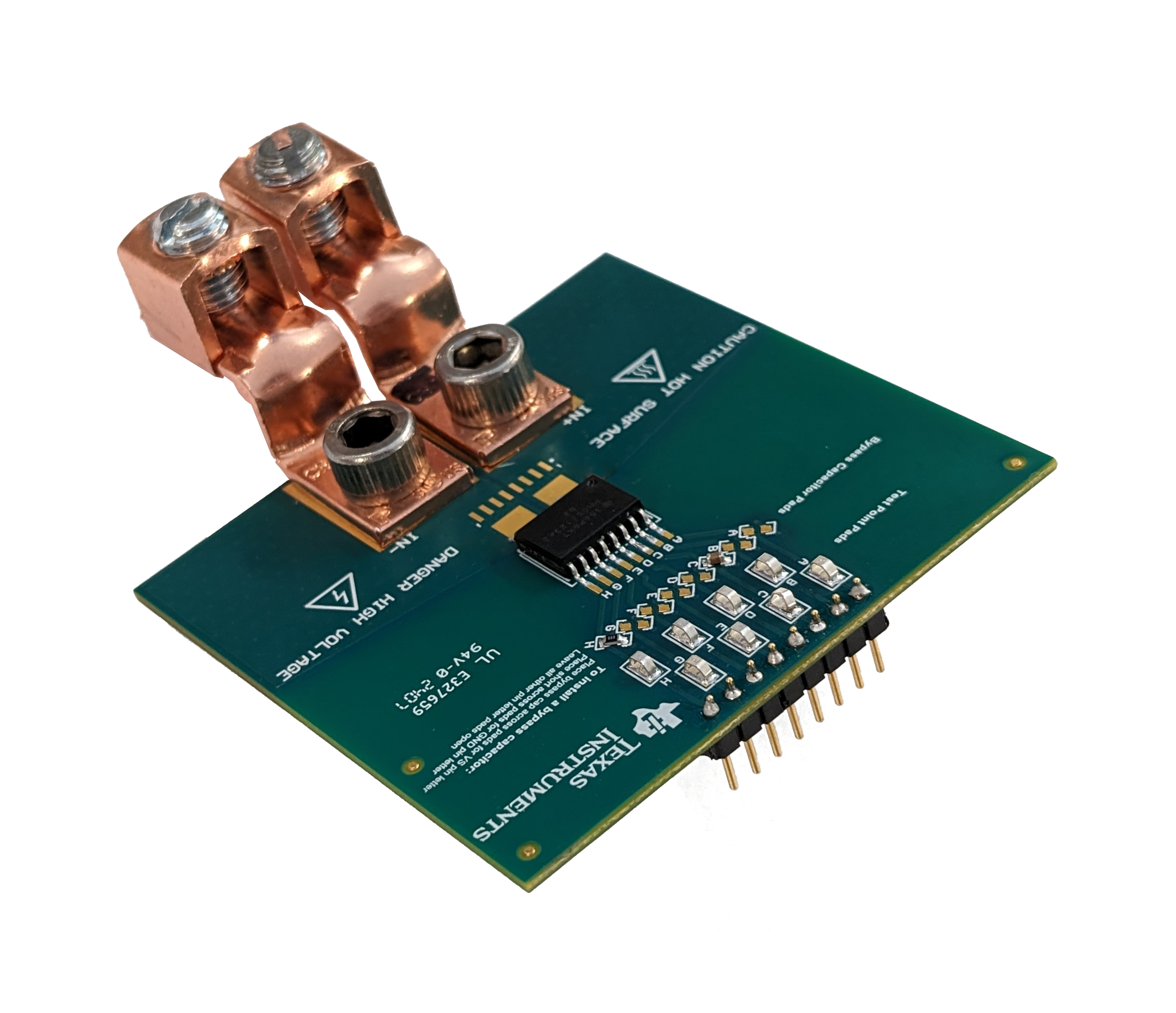
- As an example, the TMCS1123 device uses the DVG package pins 8 and 3 for GND and Vs respectively. These pins correspond to the EVM traces labeled C and H respectively, so the bypass capacitor should be soldered to C and the jumper resistor should be soldered to H. An illustration of this is shown in Figure 2-1, and a picture is shown in Figure 3-1 below.
- Solder the (optional) through-hole pin headers to the board.
- Connect the high-current input lugs to the IN+ and IN- pads with the supplied screw, lock washer, and hex nut.
- The Lugs must not touch when tightened.
- Make sure that the lugs are positioned so that the lugs make contact with the maximum possible surface area of the PCB pad.
- The connectors must be tightly fastened so that the connectors cannot be moved by hand, to a torque of about 40in-lbs.
 Figure 2-1 Fully Assembled EVM with TMCS1123 device