SBAU467A October 2024 – January 2025 ADC32RF55
- 1
- Description
- Features
- Applications
- 5
- 1Evaluation Module Overview
- 2Hardware
- 3Quick Start Guide
- 4Hardware Design Files
- 5Additional Information
- 6Related Documentation
- 7Revision History
3.5.1 8x Complex Decimation
This example uses a coherent 790MHz input on the channel A input with the ADC in a 1x averaging mode with dither enabled.
Procedure
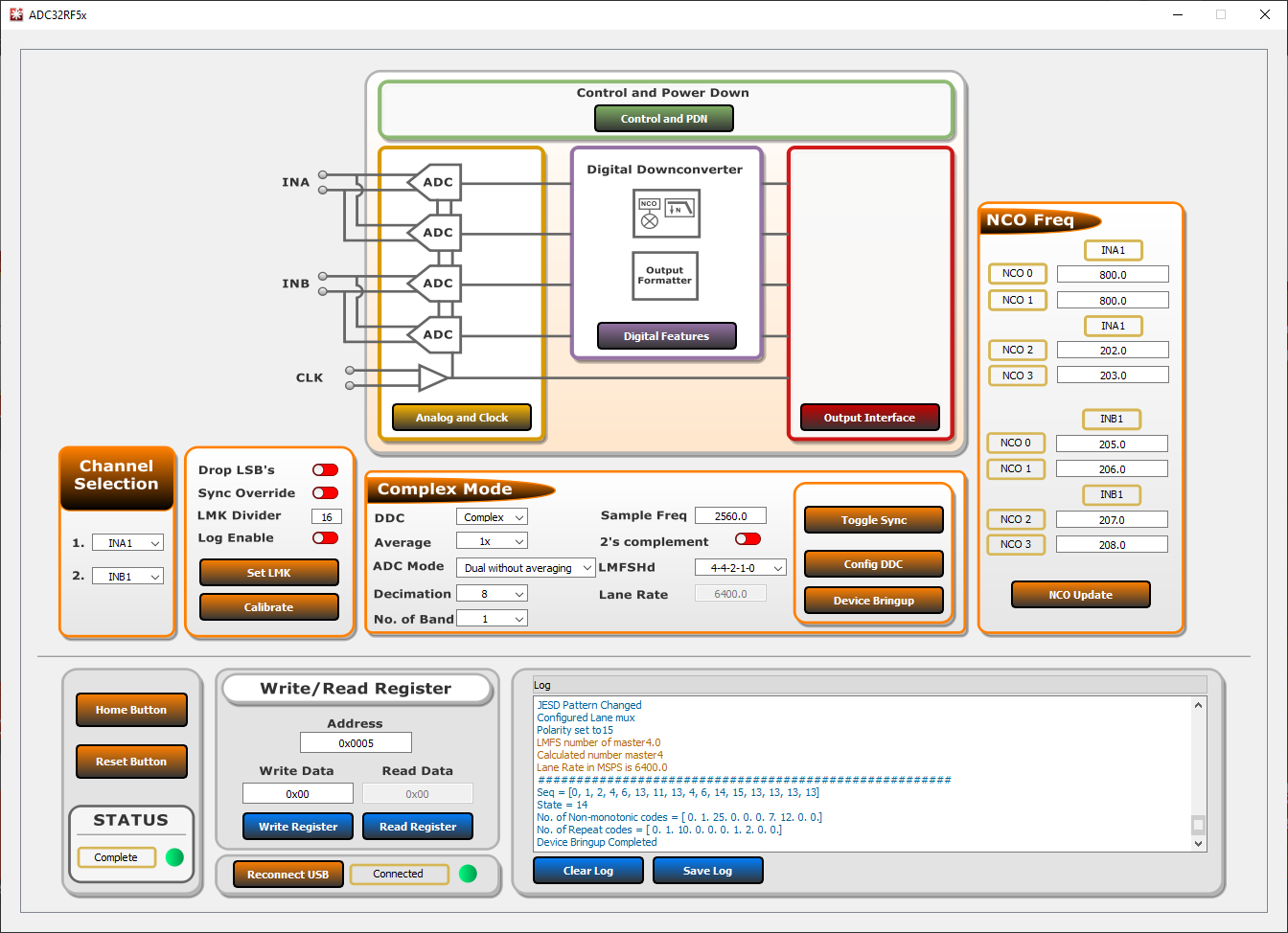
- In the Bypass Mode box, use the DDC drop-down to change to Complex Mode. Notice the box title changes to Complex Mode to reflect the current DDC operating mode.
- Use the Decimation drop-down to change the decimation to 8.
- Set the LMFSHd setting to 4-4-2-1-0.
- Set the channel INA1 NCO0 and NCO1 to 800 (MHz).
- Change LMK divider from 8 to 16.
- Once these settings are verified
and match Figure 3-6, press the Device Bringup button.
 Figure 3-6 ADC32RF5xEVM GUI, 8x
Complex Decimation, 800MHz NCO
 - Wait until after the message Device Bringup Completed appears in the Log.
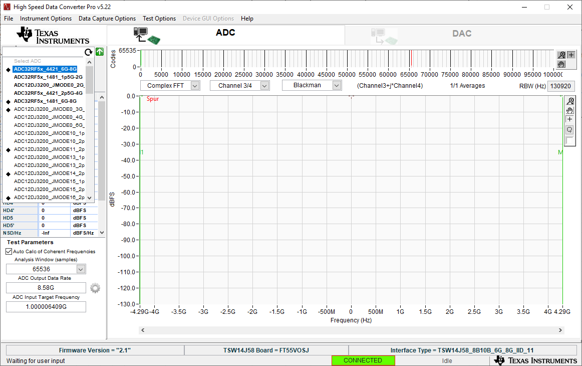
- In HSDC Pro, connect to the
TSW14J58EVM and select ADC32RF5x_4421_6G-8G as the INI file shown in
Figure 3-7.
 Figure 3-7 ADC32RF5x_4421_6G-8G
INI file
 - Update the firmware by pressing Yes on the pop-up window and waiting for the Downloading Firmware message to finish.
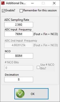
- Open the Additional Device Parameters menu by clicking on the gear next to the ADC Output Data Rate field.
- Check the box labeled
Enable? and then enter the parameters shown in Figure 3-8.
 Figure 3-8 Additional Device
Parameters , 8x complex decimation
 - Once completed, click OK.
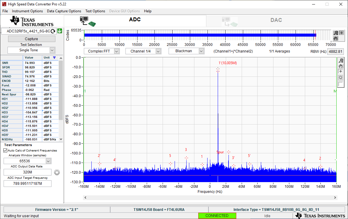
- Check the box labeled Auto Calculation of Coherent Frequencies to see the ADC Input Target Frequency change from 790M to the coherent frequency. Set the signal generator connected to channel A input to this coherent frequency.
- Change the view window from Real FFT to Complex FFT and select channel 1/4.
- Press the Capture button and a screen similar to Figure 3-9 pops up.
- Adjust signal generator output such that the measured fundamental power in HSDC Pro is at the user's desired level.
 Figure 3-9 789.995MHz Input, 8x Complex
Decimation, 1x Averaging, Dither On