SBOK092 December 2024 OPA4H199-SP
- 1
- 2
- Trademarks
- 1 Introduction
- 2 Single-Event Effects (SEE)
- 3 Device and Test Board Information
- 4 Irradiation Facility and Setup
- 5 Depth, Range, and LETEFF Calculation
- 6 Test Setup and Procedures
- 7 Destructive Single-Event Effects (DSEE)
- 8 Single-Event Transients (SET)
- 9 Event Rate Calculations
- 10Summary
- A Total Ionizing Dose from SEE Experiments
- B References
8 Single-Event Transients (SET)
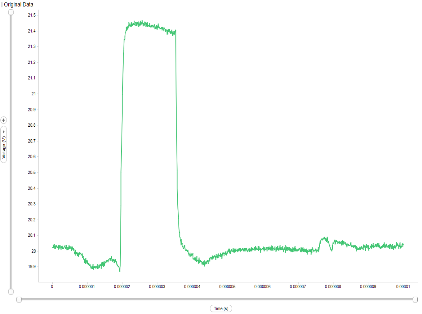
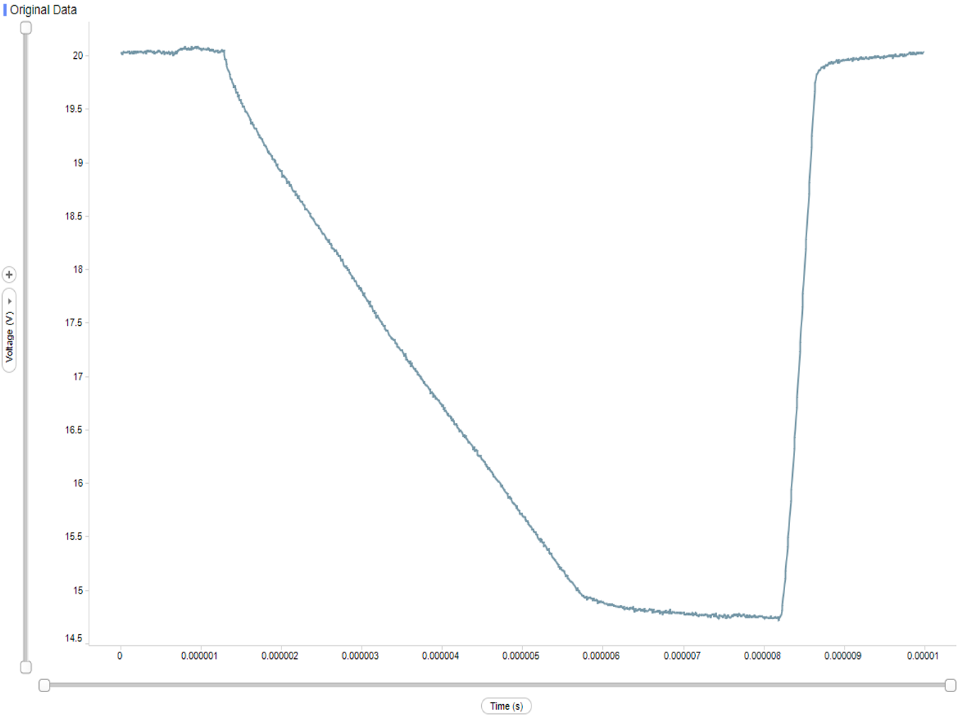
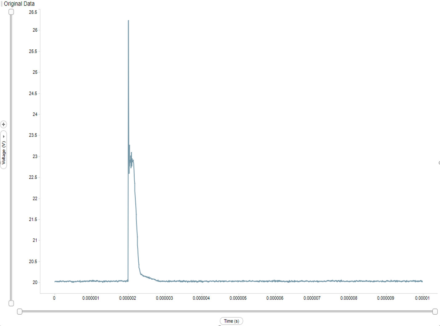
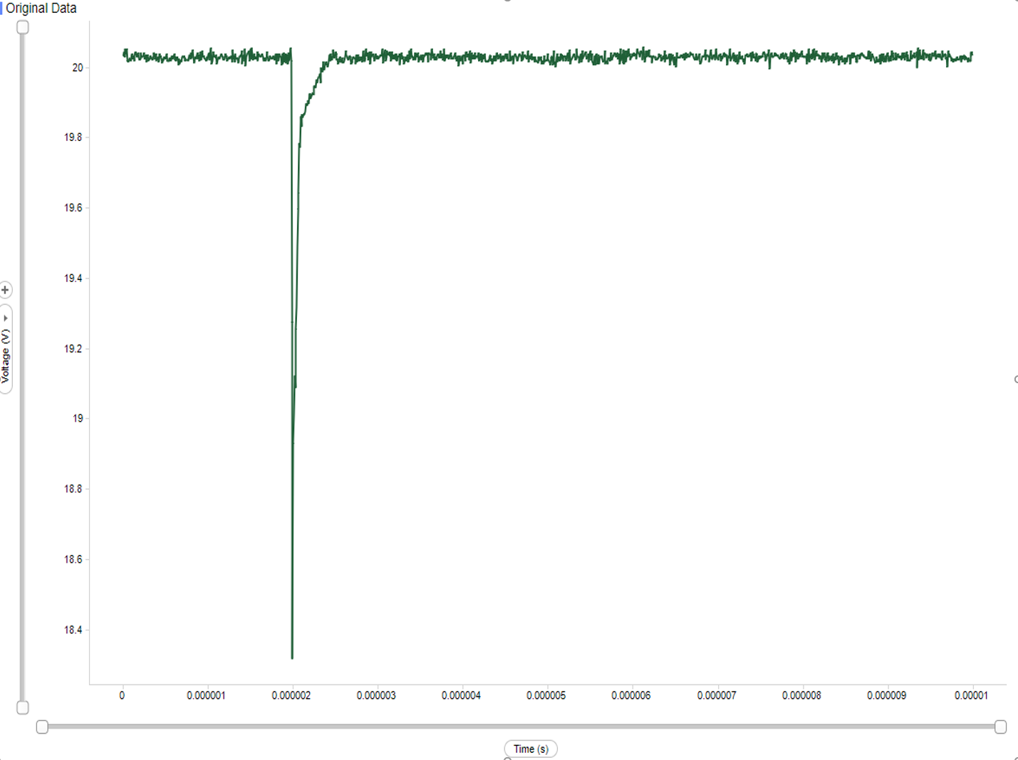
The OPA4H199-SP was characterized for SETs from 2.71MeV-cm2 /mg to 65MeV-cm2 /mg (Table 8-3 provides more information) at 40V supply voltage. The device was tested at room temperature for all SETs runs. OPA4H199-SP devices were thinned for proper heavy-ion penetration into the active circuits. Average flux of 105 ions/cm2-s and fluences of 107 ions/cm2 per run were used during the heavy ion characterization. The devices were tested under static (DC) inputs. The SETs discussed on this report were defined as output voltages excursion that exceed a window trigger set on the DPO7104C. The OPA4H199-SP was connected to a 40V supply and configured as a buffer with the comomon-mode input voltage set to 20V (midsupply). The output voltage was monitored directly to detect events. Test conditions used during the testing are provided in Table 8-3. Positive and negative upsets excursions were observed under DC test. The events were divided into short events and long events, based on the length of their duration before resolving back to the expected value. Figure 8-2 and Figure 8-2 are examples of long SET events. Figure 8-2 and Figure 8-2 are examples of long SET events. For each upset the maximum, minimum and transient recovery time was recorded. Weibull-Fit and cross section for the DC tests are shown in Figure 8-1 and Figure 8-2. The Weibull equation used for the fit is shown in Equation 1, and parameters are provided in Table 8-2. To calculate the cross section values at the different supply voltages the total number of upsets (or transients) and the fluences where combined (add together) by LETEFF to calculate the upper bound cross section (as discussed in Appendix B) at 95% confidence interval. The σPERCASE cross section presented on the summary tables, was calculated using the MTBF method at 95%.
| Run # | Unit # | ION | LETEFF (MeV × cm2/mg) | Distance (mm) | FLUX (ions × cm2/mg) | Fluence (Number ions) | Temperature (°C) | # of Long Events | # of Short Events |
|---|---|---|---|---|---|---|---|---|---|
| 20 | 6 | 141Pr | 65 | 50 | 1.15 × 10⁵ | 1.10 × 10⁷ | 25 | 67 | 161 |
| 33 | 6 | 109Ag | 51 | 75 | 1.08 × 10⁵ | 9.95 × 10⁶ | 25 | 54 | 265 |
| 34 | 6 | 109Ag | 47 | 40 | 1.06 × 10⁵ | 9.96 × 10⁶ | 25 | 29 | 272 |
| 41 | 6 | 84Kr | 32 | 75 | 1.09 × 10⁵ | 1.00 × 10⁷ | 25 | 31 | 277 |
| 42 | 6 | 63Cu | 19 | 30 | 1.01 × 10⁵ | 9.97 × 10⁶ | 25 | 24 | 246 |
| 49 | 6 | 40Ar | 8 | 30 | 1.01 × 10⁵ | 1.00 × 10⁷ | 25 | 14 | 95 |
| 50 | 6 | 20Ne | 3 | 30 | 1.17 × 10⁵ | 1.00 × 10⁷ | 25 | 3 | 21 |
 Figure 8-1 OPA4H199-SP Long SET Cross Section
and Weibull-Fit
  Figure 8-2 OPA4H199-SP Short SET Cross Section
and Weibull-Fit
 | Parameter | Long | Short |
|---|---|---|
| Onset (MeV-cm2/mg) |
1.53 |
0.90 |
| σSAT (cm2) | 6.09 × 10⁻⁶ | 2.76 × 10⁻⁵ |
| W |
31.23 |
13.14 |
| s |
0.94 |
1.06 |
 Figure 8-3 OPA4H199-SP Long SET Event Example
(up)
 Figure 8-4 OPA4H199-SP Long SET Event Example (down)
  Figure 8-5 OPA4H199-SP Short SET Event Example (up)
  Figure 8-6 OPA4H199-SP Short SET Event Example (down)