SBOU278 December   2021


  1.   Trademarks
  2. 1Overview
    1. 1.1 OPT4001YMNEVM Kit Contents
    2. 1.2 Related Documentation from Texas Instruments
  3. 2OPT4001YMNEVM Hardware
    1. 2.1 Theory of Operation for the OPT4001YMNEVM
    2. 2.2 OPT4001YMNEVM Hardware Overview
  4. 3OPT4001YMNEVM Software
    1. 3.1 Hardware Requirements
    2. 3.2 Software Installation
    3. 3.3 Typical OPT4001YMNEVM Hardware Setup
    4. 3.4 Launching the OPT4001EVM Software
    5. 3.5 OPT4001EVM Software Operation
      1. 3.5.1 Getting Started
      2. 3.5.2 Feature Descriptions
  5. 4Schematic, PCB Layout, and Bill of Materials
    1. 4.1 Flex Coupon Board
      1. 4.1.1 Schematic
      2. 4.1.2 PCB Layout
      3. 4.1.3 Bill of Materials
    2. 4.2 Rigid Coupon Board
      1. 4.2.1 Schematic
      2. 4.2.2 PCB Layout
      3. 4.2.3 Bill of Materials
    3. 4.3 Motherboard
      1. 4.3.1 Schematic
      2. 4.3.2 PCB Layout
      3. 4.3.3 Bill of Materials
  6. 5Troubleshooting
    1. 5.1 Microsoft Windows 7 Manual Driver Installation

Schematic, PCB Layout, and Bill of Materials

This EVM consists of 3 boards as shown in Figure 4-1. The flex coupon board is a flex PCB with OPT4001 IC and cutout for optimal sensor field of view. This flex board is soldered onto a rigid coupon board for added stability. The rigid coupon board contains 8 pins which allow it to plug into a socket on the motherboard. The motherboard contains an MSP430 microcontroller and plugs into a PC through the provided USB cable. This section contains the schematics, layout, and bill of materials for these 3 boards.
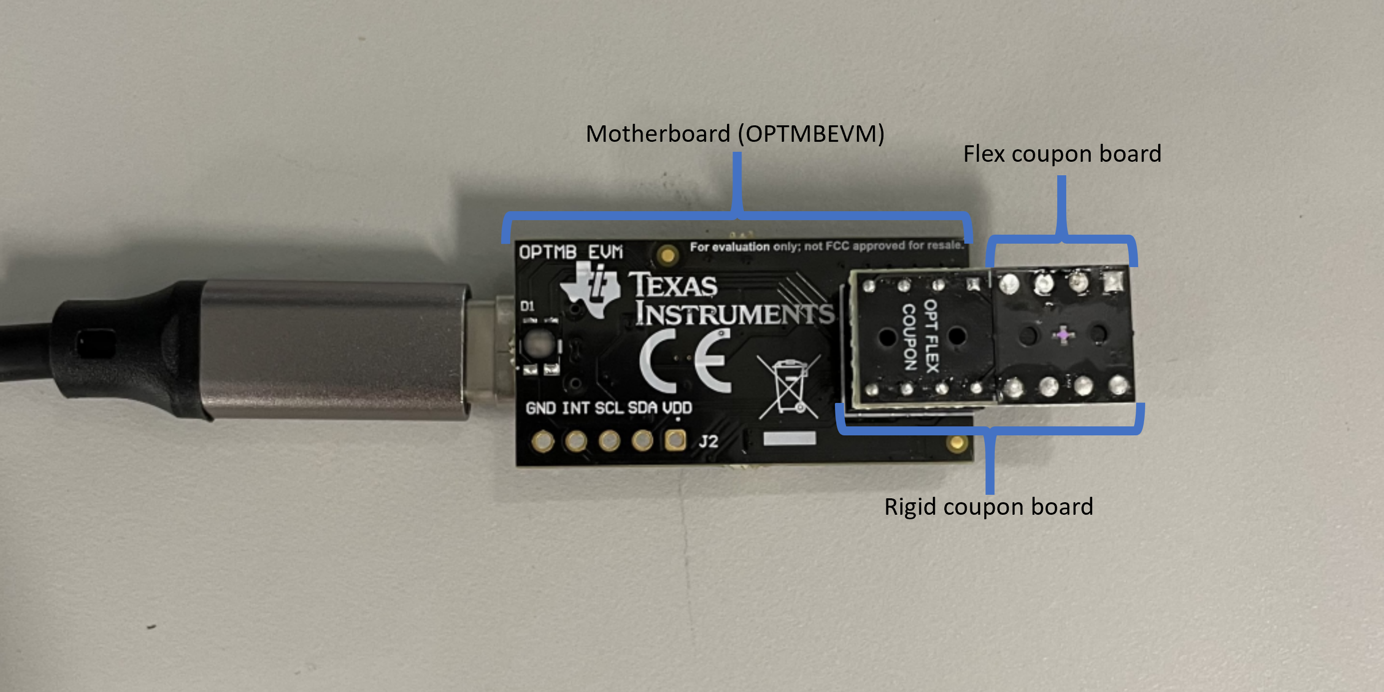
GUID-20211220-SS0I-DS2G-LV3V-P6G86L9C23CP-low.png Figure 4-1 OPT4001YMNEVM construction