SBOU278 December   2021


  1.   Trademarks
  2. 1Overview
    1. 1.1 OPT4001YMNEVM Kit Contents
    2. 1.2 Related Documentation from Texas Instruments
  3. 2OPT4001YMNEVM Hardware
    1. 2.1 Theory of Operation for the OPT4001YMNEVM
    2. 2.2 OPT4001YMNEVM Hardware Overview
  4. 3OPT4001YMNEVM Software
    1. 3.1 Hardware Requirements
    2. 3.2 Software Installation
    3. 3.3 Typical OPT4001YMNEVM Hardware Setup
    4. 3.4 Launching the OPT4001EVM Software
    5. 3.5 OPT4001EVM Software Operation
      1. 3.5.1 Getting Started
      2. 3.5.2 Feature Descriptions
  5. 4Schematic, PCB Layout, and Bill of Materials
    1. 4.1 Flex Coupon Board
      1. 4.1.1 Schematic
      2. 4.1.2 PCB Layout
      3. 4.1.3 Bill of Materials
    2. 4.2 Rigid Coupon Board
      1. 4.2.1 Schematic
      2. 4.2.2 PCB Layout
      3. 4.2.3 Bill of Materials
    3. 4.3 Motherboard
      1. 4.3.1 Schematic
      2. 4.3.2 PCB Layout
      3. 4.3.3 Bill of Materials
  6. 5Troubleshooting
    1. 5.1 Microsoft Windows 7 Manual Driver Installation

PCB Layout

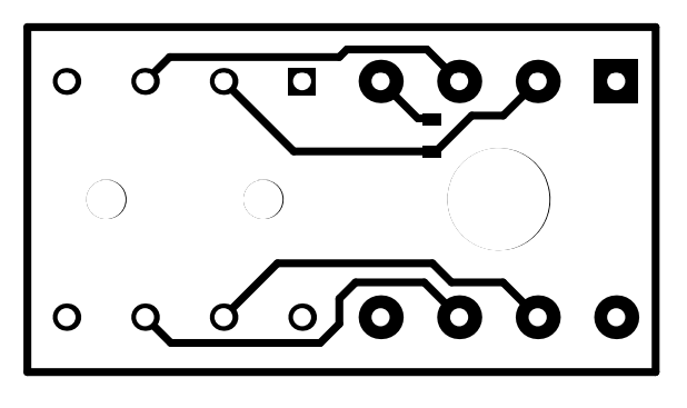
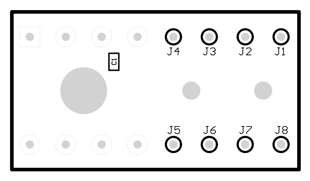
Figure 4-8 and Figure 4-9 show the top and bottom PCB layers, respectively, of the coupon rigid board. Figure 4-10 and Figure 4-11 show the assembly drawings of the top and bottom PCB layers, respectively.
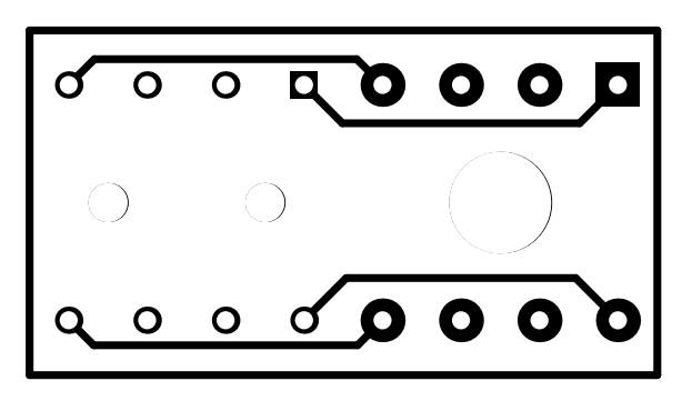
GUID-20211220-SS0I-NBCD-SC8L-0ND7LFR7JGZB-low.png Figure 4-8 PCB Top Layer
GUID-20211220-SS0I-XLLH-06FJ-XRCKVWWQGCGS-low.png Figure 4-9 PCB Bottom Layer
GUID-20211220-SS0I-7KSB-P4BT-3NMKFRCMJPFB-low.png Figure 4-10 PCB Top-Layer Assembly Drawing
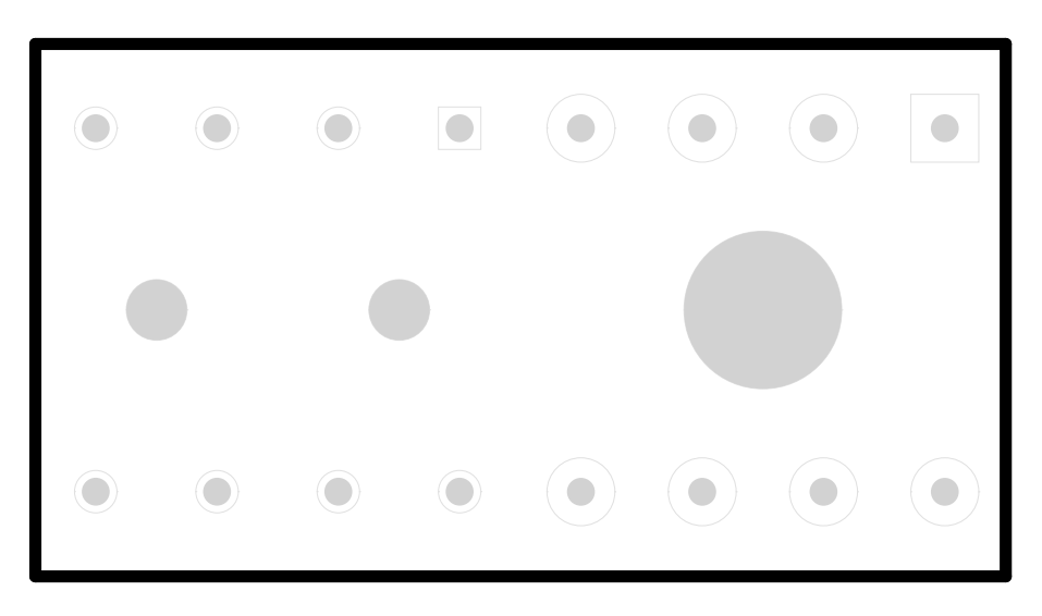
GUID-20211220-SS0I-J0VM-NJCS-VNQXRSRVCRQD-low.png Figure 4-11 PCB Bottom-Layer Assembly Drawing