SBOU293F November   2022  – December 2024


  1.   1
  2.   Description
  3.   Features
  4.   4
  5. 1Evaluation Module Overview
    1. 1.1 Introduction
    2. 1.2 OPTEVM Kit Contents
    3. 1.3 Device Information
  6. 2Hardware
    1. 2.1 OPTEVM Hardware Overview
  7. 3Software
    1. 3.1 OPTEVM Software
      1. 3.1.1 Hardware Requirements
      2. 3.1.2 Software Installation
      3. 3.1.3 Typical OPTEVM Hardware Setup
      4. 3.1.4 Launching the OPT300x/4xxxEVM Software
      5. 3.1.5 OPTEVM Software Operation
        1. 3.1.5.1 Getting Started
        2. 3.1.5.2 Feature Descriptions
          1. 3.1.5.2.1 Lux Plot
          2. 3.1.5.2.2 Mean, Std, and the Blue Slider
      6. 3.1.6 Controls
        1. 3.1.6.1 Capture Controls
          1. 3.1.6.1.1 Start Capture and Stop Capture
          2. 3.1.6.1.2 Display Sample Count
          3. 3.1.6.1.3 Save to File
        2. 3.1.6.2 Device Controls
          1. 3.1.6.2.1 Mode Select
          2. 3.1.6.2.2 Conversion Time
        3. 3.1.6.3 Operation Controls
          1. 3.1.6.3.1 Operation Select
          2. 3.1.6.3.2 Measurement/Capture Trigger
          3. 3.1.6.3.3 Oneshot Time (μs)
      7. 3.1.7 OPTxxxDTSEVM Variants
        1. 3.1.7.1 OPT4048DTSEVM
          1. 3.1.7.1.1 OPT4048DTSEVM CIE XY Window
          2. 3.1.7.1.2 OPT4048DTSEVM Lux Live Window
          3. 3.1.7.1.3 OPT4048DTSEVM Channel Live Window
        2. 3.1.7.2 OPT4060DTSEVM
          1. 3.1.7.2.1 OPT4060DTSEVM Channel Live Window
          2. 3.1.7.2.2 OPT4060DTSEVM Lux Live Window
      8. 3.1.8 Scripts Window
        1. 3.1.8.1 Additional Features of the Scripts Window
          1. 3.1.8.1.1 Hidden IDE Window
          2. 3.1.8.1.2 devInit.py
          3. 3.1.8.1.3 04-launchGUI.py
        2. 3.1.8.2 Overview of Device Registers: OPT4xxx Devices
  8. 4Hardware Design Files
    1. 4.1 Coupon Board
      1. 4.1.1 Schematic
      2. 4.1.2 PCB Layout DTS Package
      3. 4.1.3 Bill of Materials (BOM)
    2. 4.2 Motherboard
      1. 4.2.1 Schematic
      2. 4.2.2 PCB Layout
      3. 4.2.3 Bill of Materials
  9. 5Additional Information
    1. 5.1 Trademarks
    2. 5.2 Troubleshooting
      1. 5.2.1 Microsoft Windows 7 Manual Driver Installation
  10. 6Related Documentation from Texas Instruments
  11. 7Revision History

OPTEVM Hardware Overview

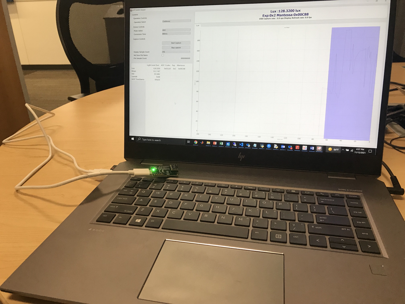
Figure 2-1 shows the system setup for the OPTEVM. The computer runs the graphical user interface (GUI) software that communicates with the OPTMB EVM board over a USB connection. The OPTMB EVM board has a USB Type C port and ships with a USB-C to USB-A cable. The OPTMB EVM board acts as a bridge between the software running on the PC and the OPTCB coupon board. The MSP430 on the OPTMB EVM board receives USB commands from the PC and communicates with the light sensor over I2C.

The OPTCB coupon board consists of the light sensor IC, decoupling capacitor, and 8 pins. The pins create connections for the power, I2C, and an interrupt signal between the OPTCB coupon board and the OPTMB EVM board. For evaluation purposes, the OPTCB coupon board can be removed from the OPTMB EVM board to use with other platforms. The OPTMB EVM board also has an unpopulated 5-pin header footprint for easy access to the supply, ground, I2C, and interrupt lines.

The EVM ships with the OPTCB coupon board plugged into the motherboard. If not already assembled, then the basic hardware setup for the OPTEVM involves plugging the coupon board into the OPTMB EVM board socket. Take special care to make sure the OPTCB coupon board is oriented correctly as shown in Figure 1-1. Then connect the USB cable. This section presents the details of this procedure.
CAUTION: Many of the components on the OPTEVM are susceptible to damage by electrostatic discharge (ESD). Customers are advised to observe proper ESD handling precautions when unpacking and handling the OPTEVM, including the use of a grounded wrist strap at an approved ESD workstation.
OPTEVM OPTEVM Hardware SetupFigure 2-1 OPTEVM Hardware Setup