SBVU085 December 2024
2.1.1 EVM Connections
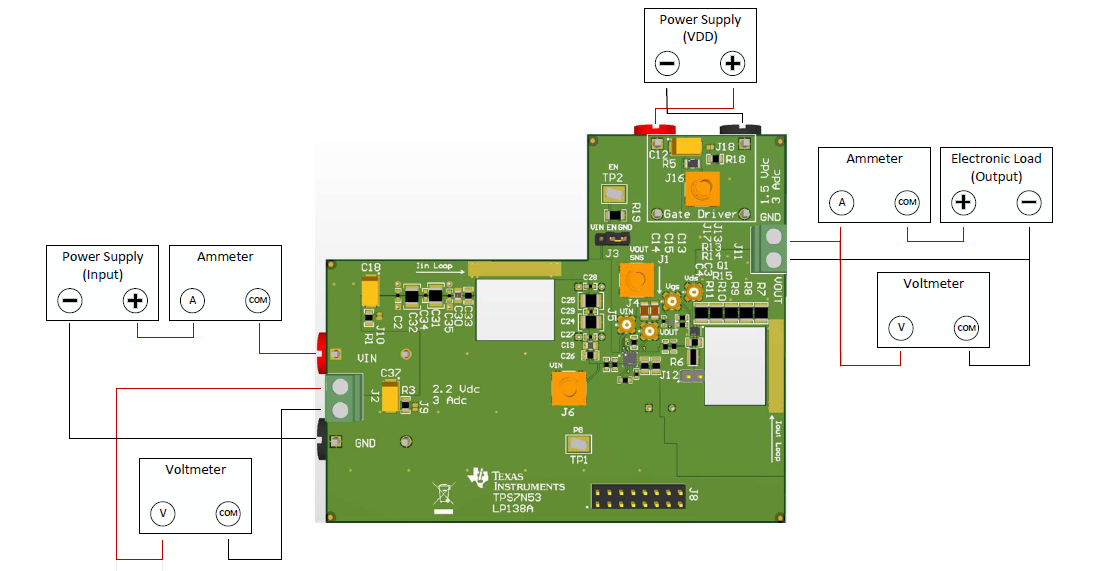
Referencing the EVM connections described in EVM Power Connections, the recommended test setup to evaluate the TPS7N53 device is shown in EVM Test Setup. Working at an ESD-protected workstation, make sure that any wrist straps, boot straps, or mats are connected and referencing the user to earth ground before handling the EVM.
 Figure 2-1 EVM Test
Setup
Figure 2-1 EVM Test
SetupCAUTION:
Refer to the TPS7N53 data sheet for additional guidance pertaining to component selection and controller operation.
Table 2-1 EVM Power Connections
| LABEL | DESCRIPTION |
|---|---|
| VIN | Input voltage power connection. |
| VDD | Load transient circuit power connection. |
Table 2-2 EVM Signal Connections
| LABEL | DESCRIPTION |
|---|---|
| PG | Open-drain, power-good indicator pin for the low-dropout regulator (LDO) output voltage. |
| SS | Soft-start connection. |
| EN | Enable connection. |
| VOUT | Regulated output voltage. |
| REF | Reference connection. |
| NR | Noise-reduction connection. |
| GND | GND connection. |