SCBA020A October   1999  – March 2020 TMS3705


  1.   Integrated TIRIS™ RF Module TMS3705 Introduction to Low-Frequency Reader
    1.     Trademarks
    2. 1 Document Overview
    3. 2 Introduction
    4. 3 Key Features of the TMS3705
      1. 3.1 PLL for the System Clock
      2. 3.2 Ceramic Resonator for Reference Oscillator
      3. 3.3 Full-Bridge Driver Stage
      4. 3.4 Fully Integrated Bandpass Amplifier
      5. 3.5 Multifunctional 2-Wire Interface
    5. 4 Sequence Control
      1. 4.1 Initialization
    6. 5 Circuit Description of the Sample RF Module
      1. 5.1 Oscillator System
      2. 5.2 Antenna Circuit
      3. 5.3 Pre-Amplifier
      4. 5.4 Interface Circuit to the Control Module
      5. 5.5 Antenna Coil
    7. 6 Regulatory Notices and Ordering
      1. 6.1 Regulatory Notices
      2. 6.2 Ordering
  2.   Revision History

Antenna Coil

Figure 4 shows the coil former of the sample antenna.

Antenna inductance ≈ 440 µH

Coil = 66 turns

Wire = enameled copper wire

Wire diameter  = 0.18 mm
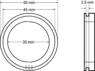
coil_cba020.gif
The antenna is designed for a free-air application. Connect a parallel resistor of 15 kΩ to the antenna to reduce the quality factor. If the antenna is mounted on a keylock, the antenna parameters must be redefined.
Figure 4. Sample Coil Former