SCDU034 may 2023
2.2 Header and Jumper Information
The TMUX4827YBHEVM has two 3-pin headers to control the power supply connection, location C2 of the TMUX4827, and the control inputs, location A2.
- Supply Header J2
Header J2 connects the VDD pin to either the external power or to ground via a jumper. If Header J2 is not connected, then the devices supply is left floating. Figure 3-1 shows header J2.
- To connect to the external supply, short the J2-2 location on the header to J2-3. The VDD_EXT terminal is now supplying the device power.
- To connect to ground, short the J2-2 location on the header to J2-1. The device supply pin is now grounded.
- To leave the device supply pin floating, leave J2-2 unconnected and floating.
- Control Header J7
Header J7 connects the SEL pin to either the external power or ground via a jumper. If Header J7 is not connected, then the devices SEL pin are left floating.
- To connect to the external supply, short the J7-2 location on the header to J7-1. The VDD_EXT terminal is now connected to the devices SEL pin.
- To connect to ground, GND, short the J7-2 location on the header to J7-3. The device SEL pin is now grounded.
- Leaving J7-2 unconnected leaves the SEL pin floating. Doing this is not recommended as the device is in an unknown state.
 Figure 2-1 Header J2 : J2-1(GND), J2-2(Connection to device VDD), J2-3 (VDD_EXT)
 Figure 2-2 Header J7 : J7-1(VDD_EXT), J7-2(Connection to device SEL), J7-3 (GND)
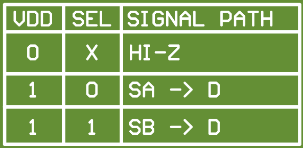
The logic of headers J2(VDD) and J7(SEL) are shown at the top side of the TMUX4827YPHEVM.
 Figure 2-3 TMUX4827YBHEVM Truth Table