SCEU027B November 2023 – October 2024 TPLD1201
PRODUCTION DATA
2.2.3 LED/Potentiometer Blocks
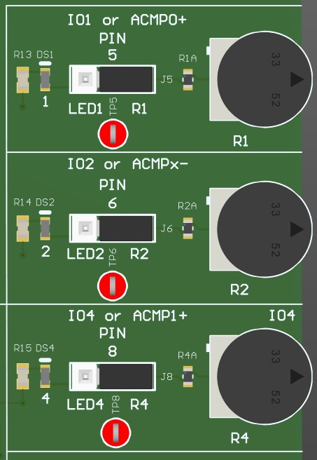
Each LED/POT block consists of a 3-state header pin that can be used the connect the corresponding GPIO pin to either a analog voltage source or an LED. The middle pin of the header connects to the corresponding GPIO pin of the TPLD. The left side of the header pin, marked LED, connects to the LED. The right side of the header pin, marked R, leads to the analog voltage source. To connect the corresponding GPIO to the LED, place a shunt between the middle pin and the LED pin. To connect the GPIO to the analog voltage source, place a shunt between the middle pin and the R pin.
The analog voltage source consists of a voltage divider using a POT. When the POT is turned fully clockwise, the analog voltage source outputs at most 0.2 V. When the POT is turned fully counterclockwise, the analog voltage source outputs at least VCC - 0.2 V.
 Figure 2-5 LED/POT Blocks