SCEU030A August 2024 – December 2024 TPLD1201
PRODUCTION DATA
3.3.1 TPLD1201 Demo Circuit
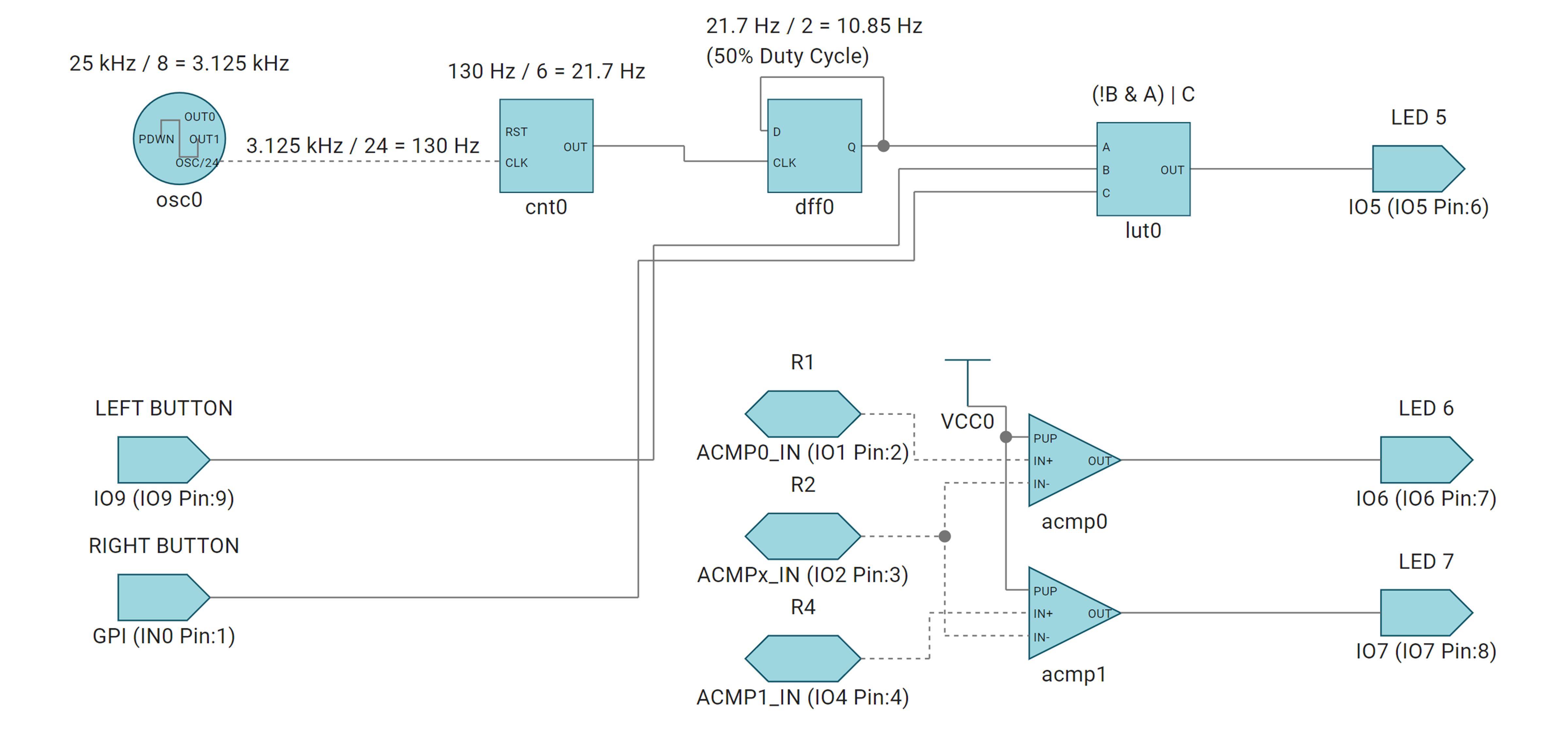
The TPLD1201 demo has four elements: analog inputs, digital inputs, digital outputs, and internal modules.
The demo has three analog inputs: ACMP0 (IO1), ACMPx (IO2) and ACMP1 (IO4). These inputs are fed into a pair of analog comparators, acmp0 and acmp1, which drive the digital outputs IO6 and IO7 respectively. When IO1 is held at a higher voltage than IO2, acmp0 drives IO6 high. When IO4 is held at a higher voltage than IO2, acmp1 drives IO7 high.
The demo uses an internal oscillator (osc0) with a frequency of 25kHz, which is divided by eight to 3.125kHz. A binary counter (cnt0) further divides the frequency by 24Hz to 130Hz, before using the divided oscillator as an input. The counter counts to 6, then outputs a high pulse and resets the count, effectively dividing the frequency of the signal by 6 to 21.7Hz. The output of the binary counter is used as the clock input of a flip-flop (dff0) with an inverted output that is used as the data input, reducing the frequency of the signal to 10.85Hz and changing the signal from being a pulse to a signal with a 50% duty cycle. The output of the flip-flop is then used as the A input of a look-up table (lut0).
The demo uses two digital inputs: IO9 and GPI. The two digital inputs are fed into the B and C inputs of the look-up table lut0, respectively. The look-up table uses the equation (!B & A) | C, so when neither of the digital inputs are high, the output of the look-up table follows the A input, which is the output of the flip-flop (dff0). When the GPI input is high, the look-up table outputs high, and when the IO9 input is high, the look-up table outputs low. The output of the look-up table drives the digital output IO5.
 Figure 3-8 TPLD1201 EVM Demo