SCLA073 October 2024 TPLD1201 , TPLD1201-Q1
4 Synchronizing Signals Example
The delay generator macro-cell can be utilized to synchronize two signals. The delay generator will delay an input signal by td = (DATA + td_err + 2)/fclk, where td_err is error due to phase shifts between the input and the clock and fclk is the frequency of the signal passed into the clock input of the delay generator. One caveat to properly use the delay generator is the input signal’s pulse width (high and low) must be greater than three times the period of the clock input.
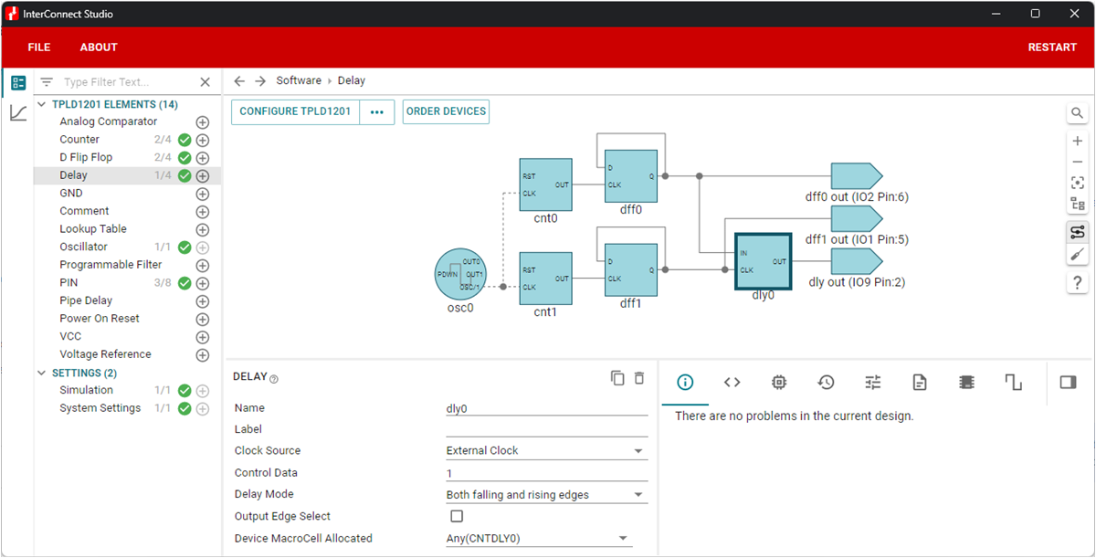
The circuit shown in Figure 4-1 generates two signals, one outputting at ~357Hz and the other at ~4.17kHz. The slower signal should be routed into the IN port of the delay generator, and using the External Clock option, the faster signal should be routed into the CLK port.
 Figure 4-1 Synchronizing Signals Example
Circuit
Figure 4-1 Synchronizing Signals Example
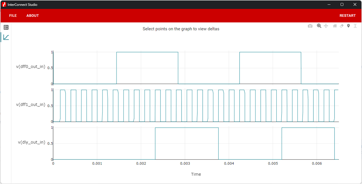
CircuitSimulation results in ICS and measured logic analyzer captures on the TPLD1201 can be found in Figure 4-2 and Figure 4-3, respectively. As evident in the images, the dff0_out and dff1_out signals were initially asynchronous and dly0 was utilized to synchronize dff0_out to dff1_out. Note: if the frequency of the two signals are not factors, the delay will result in a slight distortion of the input signal.
 Figure 4-2 ICS Simulation of
Synchronizing Signals Circuit
 Figure 4-3 Logic Analyzer Capture of
Synchronizing Signals Circuit