SCLA078 October 2024 TPLD1201-Q1
Introduction
Motor speed is a key parameter in traction inverter systems for both safe operation and accurate control, and is obtainable from the position or current sensor and calculated by a microcontroller unit (MCU). To meet the requirement of functional safety, a redundancy motor-speed detection circuit for permanent magnet synchronous motor (PMSM) is often required to decide which safe state the motor enters, in case of a detected fault. For example, when a failure in an MCU occurred, the system enters the safe state with the gate drivers blocked. However, there are two safe states for motor to enter. One safe state is Active Short Circuit (ASC) at high motor speed. In ASC, the upper or lower SiCs/IGBTs are switched on to short the motor and protect traction inverter from overvoltage. If the motor speed is low, entering ASC leads to unwanted high brake torque. Hence, the motor enters the second safe state freewheeling. In this mode, all of the SiCs/IGBTs are switched off to slow down the car. It is vitally important to obtain the safe state signal from another speed detection circuit without an MCU.
TPLD1201-Q1 for Motor Speed Detection
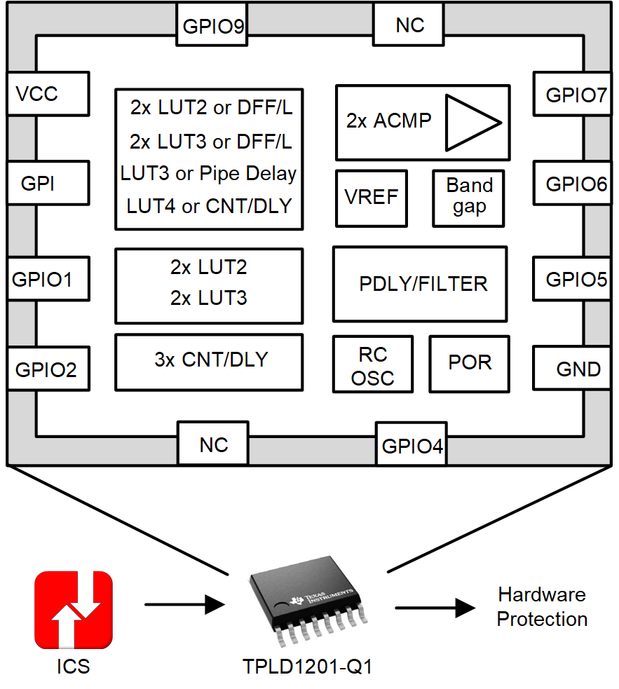
One common frequency detection circuit is applied with multiple discrete logic devices and analog devices, which occupies a large printed board circuit (PCB) area with an increasing BOM count. Texas Instruments proposes a new motor-speed detection answer with the TPLD1201-Q1, a programmable logic device in the TPLD family. Figure 1 shows the functional block of the TPLD1201-Q1, with several integrated programmable macro-cells:
- 2-, 3-, and 4-bit lookup tables (LUT)
- D flip-flops or latches with and without reset or set options
- 8-stage, 2-output pipe delay
- Selectable counters or delay generators
- Programmable deglitch filter or edge detector
- Analog comparators with selectable VREF and input gain
- Internal voltage reference fixed or ratiometric
- 25-kHz, 2-MHz RC oscillator with internal divider stages
The motor-speed detection method with TPLD1201-Q1 has several features and system benefits:
- 3.3V ASC digital output and 0V freewheeling digital output
- Programmable device for flexibly design with GUI
- Notably small size and PCB area needed with a BOM count of 1
- Very easy to design, Texas Instruments provides a high-performance design example which requires minor modifications to parameters for specific applications
- No MCU or external voltage reference needed
 Figure 1 Functional block of TPLD1201-Q1
For redundancy motor speed detection, only a portion of the functionality of TPLD1201-Q1 is used, meaning that many other FUSA functions can be integrated to remove more other digital devices. Texas Instruments provides an InterConnect Studio (ICS) for configuring TPLD1201-Q1. ICS provides a graphical drag and drop interface for generating the necessary binary string.
Design Example for Motor Speed Detection with TPLD1201-Q1 and ICS
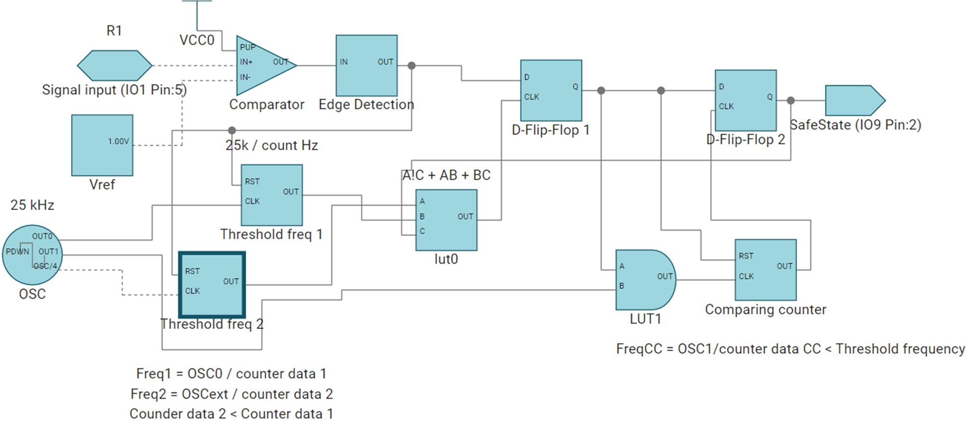
The example of motor speed detection design described in this section is developed by Texas Instruments. It is easy to set the threshold frequency by simply modifying some parameters in the example file. The circuit diagram for motor speed detection in shown in Figure 2. The sensing signal routes from the current or position sensor, and is compared with internal voltage reference to generate a pulse wave. Then, with the post digital circuits, there is a safe state output related to the input frequency. If the input frequency is greater than threshold, the safe state is high; if the input frequency is lower than threshold, the safe state is low. For hardware protection, connect the safe state signal to the ASC pin from gate drivers (such as UCC5880-Q1). Set hysteresis to avoid the bounce at the threshold frequency.
 Figure 2 Circuit Diagram for Motor
Speed Detection with TPLD1201-Q
Figure 2 Circuit Diagram for Motor
Speed Detection with TPLD1201-QThe programming circuit for motor speed detection in ICS is shown in ICS Programming Circuit for Motor Speed Detection in TPLD1201-Q1. Firstly, the input signal is compared with the internal voltage reference to generate a pulse wave, and then the rising edge is detected to eliminate the impact caused by the amplitude and duty cycle. The rising edge signal is routed in both the reset of the threshold frequency setting counter and the D-Flip-Flop 1. If the input frequency is greater than countering frequency, the output of D-Flip-Flop is high. If the input frequency is lower than countering frequency, the output of D-Flip-Flop is a pulse wave. Then, the signal is connected to a series of circuit to transfer the pulse wave into low voltage composed of a comparing counter, an AND circuit and a D-Flip-Flop 2. Two threshold frequency counters are implemented to set hysteresis.
 Figure 3 ICS Programming Circuit for Motor Speed Detection in TPLD1201-Q1
Using Figure 3, it is easy to set the threshold frequency by designating the counter data of the three counters, which is derived in Equation 1.
Here shows the instruction on setting the parameters with an 100Hz threshold frequency design example. Set the three threshold frequencies at around 100Hz. Select the parameter using the following points:
- OSC0 = 25kHz, Counter Data 1 = 250. Calculated Threshold Freq 1 = 100Hz
- OSCext = 25kHz, Counter Data 2 = 220. Calculated Threshold Freq 2 = 113.6Hz
- OSC1 = 12.5kHz, Counter Data CC= 132. Calculated Threshold Freq 1 = 94.7Hz
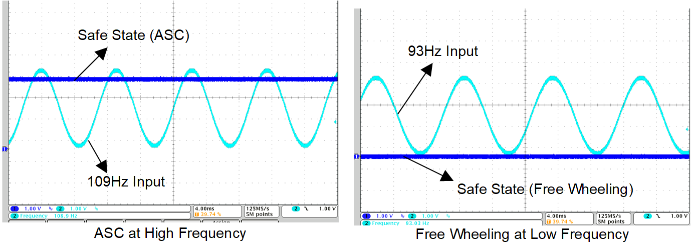
Using the above parameters, the output safe state is high when the input frequency greater than threshold frequency with some hysteresis, and is low when the input frequency is lower than threshold frequency with some hysteresis. Figure 4 shows the waveforms of the input and output signals.
 Figure 4 Results of Sine Input and Safe State Output
Links to TPLD1201-Q1
Texas Instruments, Programmable Logic Device with Eight General Purpose Input or Outputs (GPIOs), product page
Texas Instruments, TPLD1201 Evaluation Module with a DGS Package Socket, product page
Texas Instruments, Programmer Kit Compatible with TI Programmable Logic Devices (TPLD) Evaluation Modules, product page