SCPA074 September 2024 TPLD1202
2 Utilizing the Reset Input of the Pattern Generator
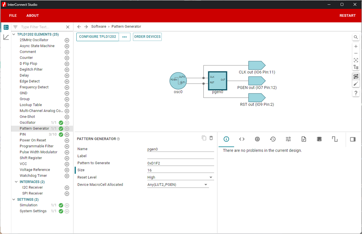
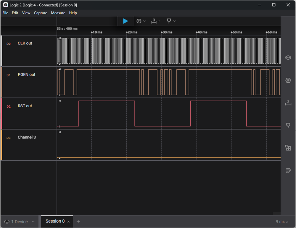
A reset signal can be added to the circuit to restart the pattern generator. The PGEN macro-cell defaults to an active-low reset. While in the reset state, the PGEN will continually output the MSB of the specified pattern. After the reset is de-asserted, the pattern will begin to output on the next rising edge of the CLK input. Figure 2-1 shows an example of the PGEN configured to output a 16-bit pattern, 0xD1F2, with an active-high reset. As shown in Figure 2-2, while the RST signal is high, the output of the PGEN remains high since the MSB of the pattern is a 1.
 Figure 2-1 PGEN With Reset (16-bit pattern, 0xD1F2) Example Configuration in ICS
 Figure 2-2 Logic Analyzer Capture of PGEN With Reset (16-bit Pattern, 0xD1F2)
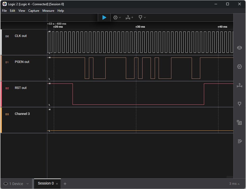
 Figure 2-3 Logic Analyzer Capture of PGEN With Reset (16-bit Pattern, 0xD1F2, Zoomed)