SCPA074 September 2024 TPLD1202
1 Configuring the Pattern Generator in TPLD Using InterConnect Studio (ICS)
The pattern generator (PGEN) macro-cell, shown in Figure 1-1, within TPLDs can be configured to generate 1-bit to 16-bit patterns and the reset input polarity can be set to active-low or active-high. The pattern is continually clocked out from most significant bit (MSB) to least significant (LSB) on the rising edge of the CLK input as long as it is not in a reset state. While in the reset state, the output will default to the first bit of the specified pattern. Figure 1-1 Pattern Generator Macro-cell Block Diagram
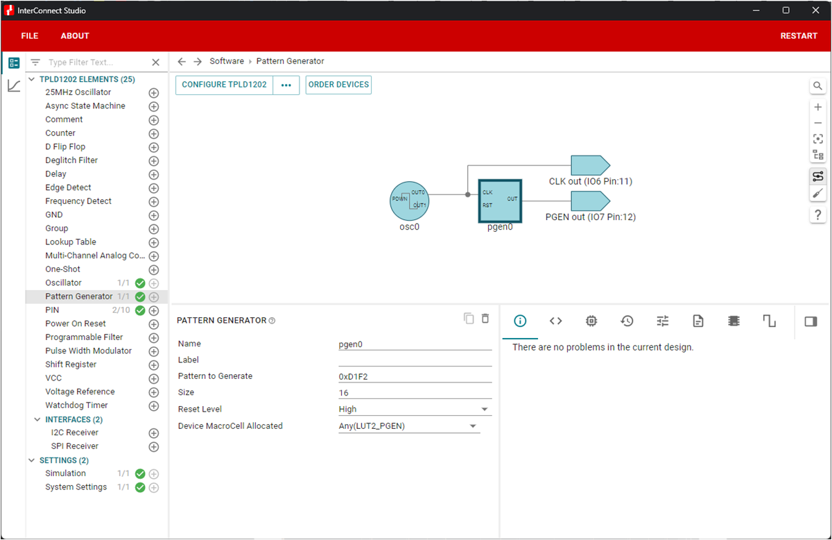
 Figure 1-2 Pattern Generator (PGEN) Configuration in ICS
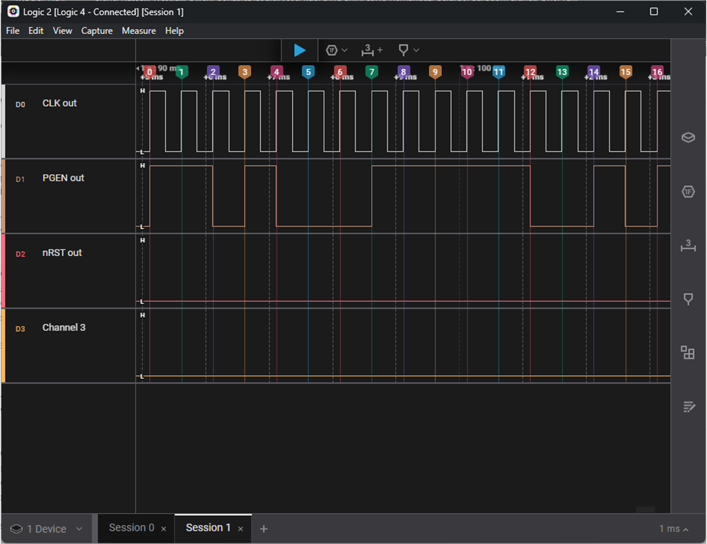
 Figure 1-3 Logic Analyzer Capture of Pattern Generator Output
 Figure 1-1 Pattern Generator Macro-cell Block Diagram
The circuit configured in InterConnect Studio (ICS), shown in Figure 1-2, generates a 16-bit pattern of 0xD1F2 that is clocked out at 2kHz using the internal oscillator. The pattern can be provided in decimal (0 to 65535) or hexadecimal (0x0000 to 0xFFFF), any bits not specified are defaulted to 0, and is stored in binary from MSB to LSB. Depending on the designated size (n), the n-bit pattern is clocked out from bit n-1 to bit 0, regardless of how many bits are stored in the non-volatile memory.
 Figure 1-2 Pattern Generator (PGEN) Configuration in ICS
 Figure 1-3 Logic Analyzer Capture of Pattern Generator Output