SLAAE25 May 2021 MSP430FR2355 , MSP430FR2355
5.2 Sample and Measurement Sequence
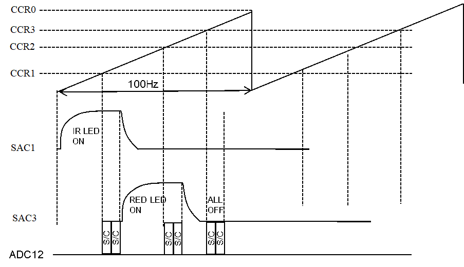
A Timer is used to control the multiplex sequence and automatically start the ADC conversion.
In this timer periods, set three CCRx values for comparison, switch the LED in each comparison interrupt and run ADC acquisition.
- Timer Start:
- Trigger SAC1 to lightt up the IR LED
- CCR1 Interrupt:
- Enable ADC to capture IR LED TIA and PGA signal
- Close SAC1
- Trigger SAC3 to lightt up the RED LED
- CCR2 Interrupt:
- enable ADC to capture RED LED TIA and PGA signal
- Close SAC3
- CCR3 Interrupt:
- enable ADC to capture ambient light TIA and PGA signal
The ADC conversion is triggered automatically. It takes two samples: one of the SAC0 output for DC tracking and one of the SAC2 output, to calculate the heart beat and oxygen level.
To conserve power, at the completion of the ADC conversion an interrupt is generated to tell the MCU to switch off the LED.
 Figure 5-2 Sample and Measurement Sequence