SLAAEC6A October 2023 – January 2024
- 1
- Description
- Get Started
- Features
- Applications
- 6
- 1Evaluation Module Overview
-
2Hardware
- 2.1 System Overview
- 2.2
Hardware Overview
- 2.2.1 AC-MB Settings
- 2.2.2 TAx5x1xQ1EVM-K Hardware Settings
- 2.2.3 Diagnostics Hardware Setup
- 2.2.4 GPIO1 Hardware Configurations
- 2.2.5 GPO1A Hardware Configurations
- 2.2.6 GPI1A Hardware Configurations
- 2.2.7 GPI2A Hardware Configurations
- 2.2.8 I2C Address Hardware Configurations
- 2.2.9 Audio Serial Interface Hardware Configurations
-
3Software
- 3.1 Software Description
- 3.2 PurePath Console 3 Installation
- 3.3
TAx5x1x-Q1 EVM GUI
- 3.3.1 Software Overview
- 3.3.2 Configuration View
- 3.3.3 End System Integration View
- 3.3.4 Register Map View
- 3.3.5 Preset Configuration
- 3.3.6 I2C Monitor View
- 3.4 Configuration Examples
- 4Hardware Design Files
- 5Additional Information
- 6Revision History
2.2.2.2.1 TAx5x1x-Q1 Analog Audio Output
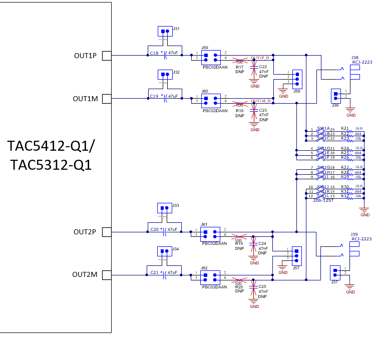
The EVM analog audio output port provides options for AC/DC-coupled and filter or filter-less paths for easy evaluation. By default, the filter components are not populated.
Switch SW1 allows users to select respective loads for each output pair for 16 Ω, 604 Ω, or 10 kΩ if needed. These resistors are for quick evaluation and can be bypassed for actual load. SW1 and the output RCA connectors are located on the top left-hand side, shown in Figure 3-13.
 Figure 2-12 TAC5x12-Q1 EVM Output Architecture for Channel 1 and 2
OUT1 and OUT2 audio output pins have connection options with external load or the on-board load selections. A pair of RCA connectors, white from OUTP and red from OUTM, allow users to connect to external devices as differential or single-ended. Jumper header J36 or J37 must be populated if single-ended is desired or removed for differential configuration.
| SW1 pin | Load Configuration | Resistor Rating | Output Module Register Setting |
|---|---|---|---|
| 1, 4, 7, 10 | 16 Ω | 0.5 W | B0_P0_R101 |
| 2, 5, 8, 11 | 604 Ω | 0.125 W | B0_P0_R101 |
| 3, 6, 9, 12 | 10 kΩ | 0.4 W | B0_P0_R101 |
 Figure 2-13 TAC5x12-Q1 Analog Output Connections
For TAC5411-Q1 or TAC5311-Q1, OUT2 components are not populated.