SLAAEC6A October 2023 – January 2024
- 1
- Description
- Get Started
- Features
- Applications
- 6
- 1Evaluation Module Overview
-
2Hardware
- 2.1 System Overview
- 2.2
Hardware Overview
- 2.2.1 AC-MB Settings
- 2.2.2 TAx5x1xQ1EVM-K Hardware Settings
- 2.2.3 Diagnostics Hardware Setup
- 2.2.4 GPIO1 Hardware Configurations
- 2.2.5 GPO1A Hardware Configurations
- 2.2.6 GPI1A Hardware Configurations
- 2.2.7 GPI2A Hardware Configurations
- 2.2.8 I2C Address Hardware Configurations
- 2.2.9 Audio Serial Interface Hardware Configurations
-
3Software
- 3.1 Software Description
- 3.2 PurePath Console 3 Installation
- 3.3
TAx5x1x-Q1 EVM GUI
- 3.3.1 Software Overview
- 3.3.2 Configuration View
- 3.3.3 End System Integration View
- 3.3.4 Register Map View
- 3.3.5 Preset Configuration
- 3.3.6 I2C Monitor View
- 3.4 Configuration Examples
- 4Hardware Design Files
- 5Additional Information
- 6Revision History
3.3.2.6.2 Programmable Biquads Tab
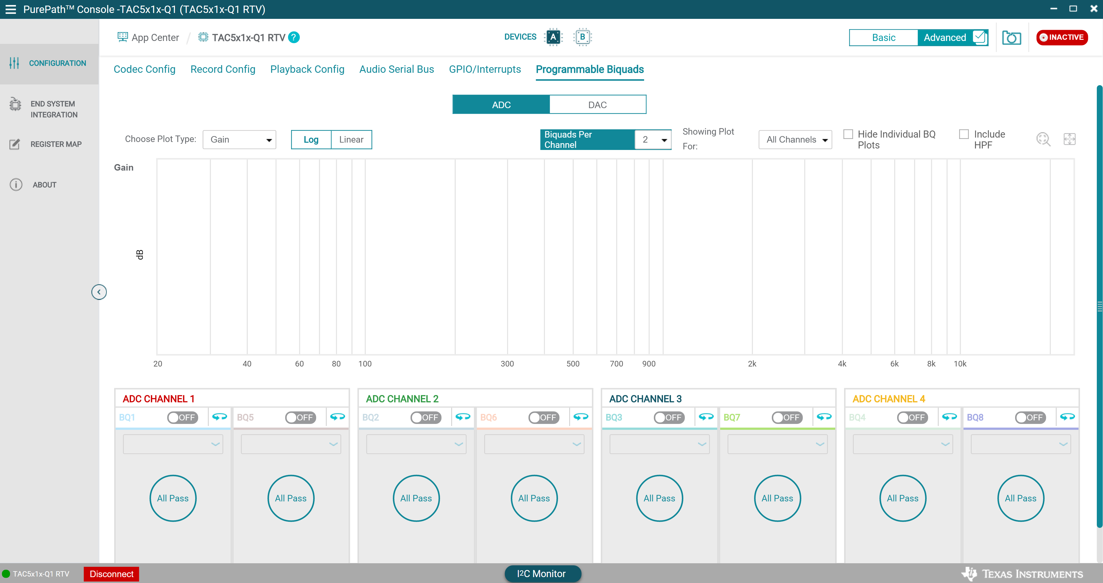
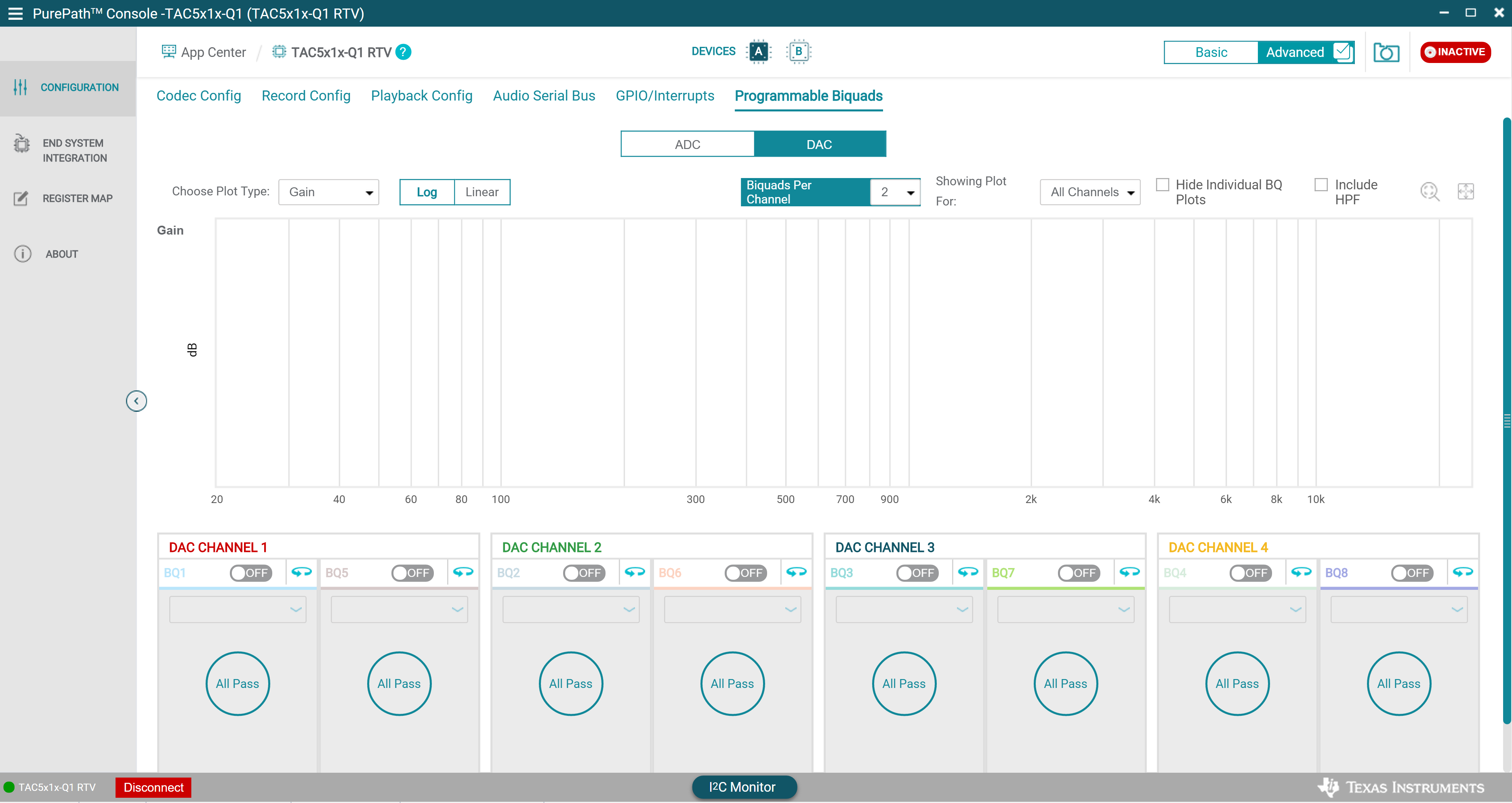
Configuration of the biquad filters is made easy with the GUI in the programmable biquads tab. Biquad coefficients can be generated using the filter designers within PPC3 or biquad coefficients can be manually entered into the coefficients cells obtained from external filter tool. Each biquad can be configured individually, the gain and phase responses can then be shown for individual channels or all channels. Note that PPC3 uses the detected sampling rate from the audio serial bus tab to determine the biquad coefficients. The TAx5x1x-Q1 device must receive the desired sampling rate when the audio serial bus tab is opened, and the clock monitor must be updated by clicking the Read button. If no EVM is connected, PPC3 assumes sampling rate of 48 kHz for all biquad calculations.
 Figure 3-24 Programmable ADC Biquads Tab
 Figure 3-25 Programmable DAC Biquads Tab