SLAAED4 October 2023 TAA5412-Q1 , TAC5311-Q1 , TAC5312-Q1 , TAC5411-Q1 , TAC5412-Q1
2.1 Differential AC Coupled Configuration
In AC-Coupled differential input configuration, the common mode voltage, can be configured through an external bias resistor and MICBIAS. This Excel tool TAX5X1X-Q1-EXT-RES-CALCULATOR can be found from this link The tool calculates this external resistance based on input swing and the desired MICBIAS voltage.
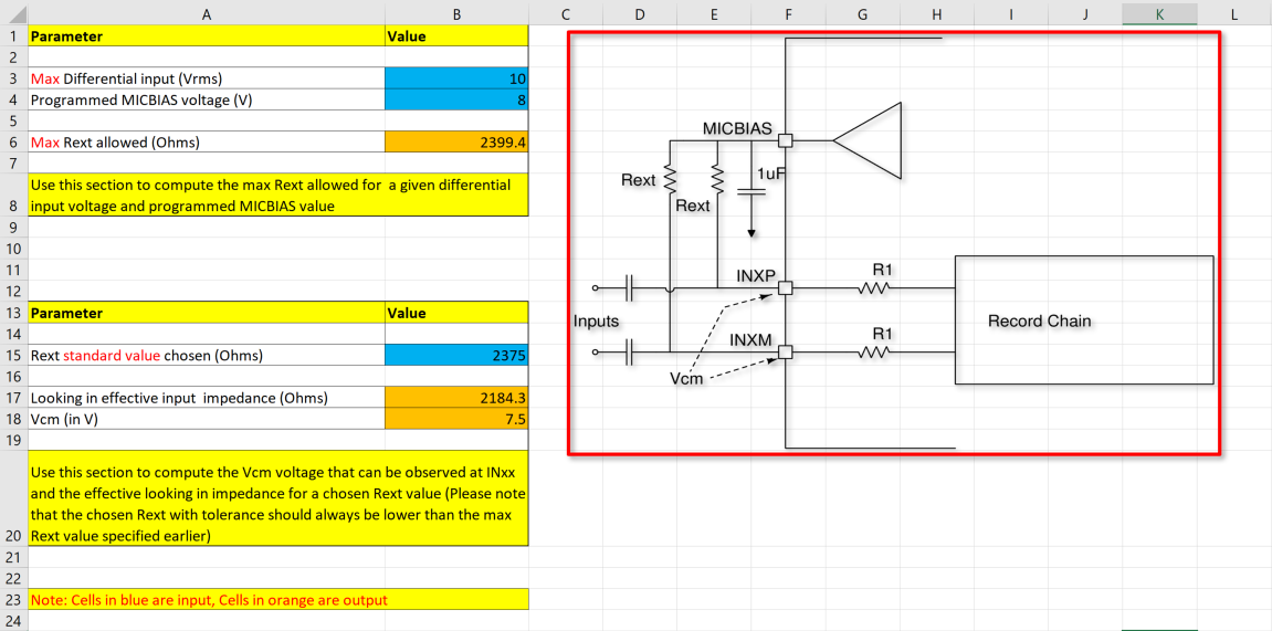 Figure 2-1 AC-Coupled External Resistor
Calculator
Figure 2-1 AC-Coupled External Resistor
CalculatorAs an example using differential input swing of 10 Vrms and 8 V MICBIAS, the maximum resistance allowed is 2399.4 Ω and the closest standard resistance is 2375 Ω. Based on this standard value resistance, the effective impedance looking into the device is about 2184 Ω. This effective input impedance forms a high pass filter with the external capacitor for these inputs and Vcm is the respective common voltage.
The following script configures the device to differential AC-Coupling mode.
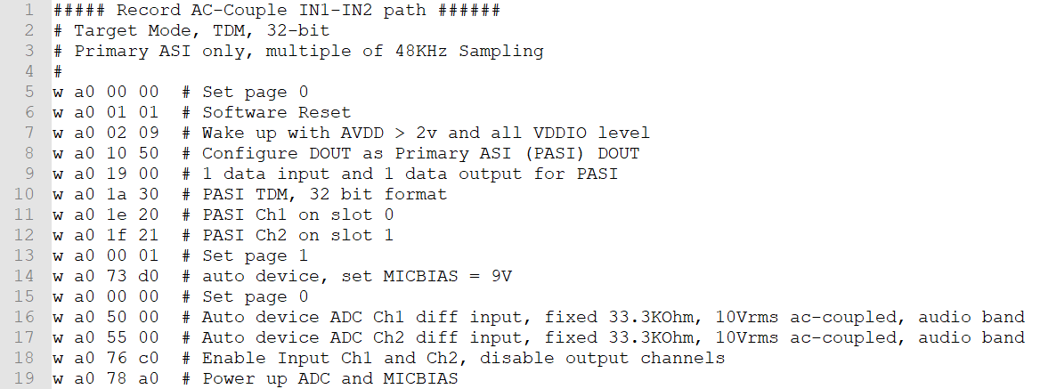 Figure 2-2 Differential AC-Coupled
Register Setting
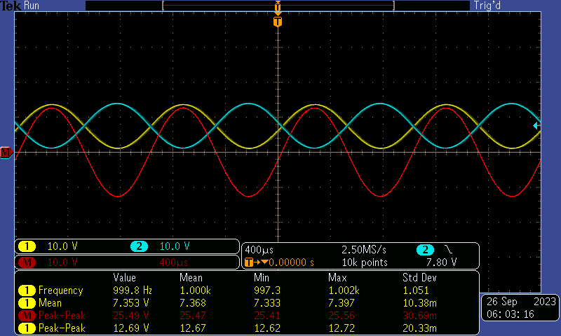 Figure 2-3 Differential AC-Coupled
Input Swing at -1dBrG (0dBrG = 10Vrms)
Figure 2-3 Differential AC-Coupled
Input Swing at -1dBrG (0dBrG = 10Vrms)A frequency plot of the Dynamic Range with -60dBrG input and SNR with input AC signal shorted to ground are provided here.
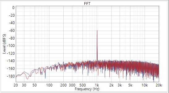 Figure 2-4 Differential AC-Coupled
Dynamic Range at -60dBrG Input
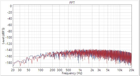 Figure 2-5 SNR with Input AC Signal
shorted to GND
Figure 2-5 SNR with Input AC Signal
shorted to GNDTable 2-2 summarizes the performances for the different device variants.
| THDN (at-1dBrG) | DR (dB) | SNR (dB) | ||||||
|---|---|---|---|---|---|---|---|---|
| TAC541x | TAA541x | TAC531x | TAC541x | TAA541x | TAC531x | TAC541x | TAA541x | TAC531x |
| -101 | -100 | -89 | 112 | 112 | 101 | 112 | 112 | 101 |