SLAAED8 October 2024 TAC5212 , TAC5412-Q1
4.4.2 Continuous Pulse Mode
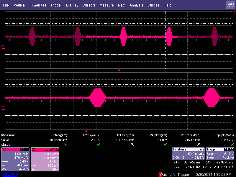
SG2 in Continuous Pulse Mode (CPM) generates repeatable pulses with defined restart and sustain time intervals. These two timers are configured based on the number of samples per second of the operating sampling rate, fs. Refer to Table 3-3.
SG2 in CPM is subject to aliasing if the Nyquist frequency, fs/2 is reached before the end of a sustain time interval. An acceptable end frequency to avoid aliasing can be generated using the timing formulas from Section 4.4.1. These formulas help select an acceptable end-frequency below the Nyquist point.
The ADSR note acknowledgement script must be executed before other ADSR paramters for CPM. However, ADSR enabling script is not needed at the end of CPM script.
# Key: w a0 XX YY ==> write to I2C address 0xa0, to register 0xXX, data 0xYY
# # ==> comment delimiter
#
#The following list gives an example sequence of items that must be #executed in the time between powering the device up and reading data #from the device. Note that there are other valid sequences depending #on which features are used.
#See the corresponding EVM user guide for jumper settings and audio #connections.
#
# Line-Out Fully-Differential 2-channel : OUT1P_M- Ch1, OUT2P_M- Ch2.
# FSYNC = 48 kHz (Output Data Sample Rate), BCLK = 12.288 MHz (BCLK/FSYNC = 256) ###################################################################

#Continuous pulse mode script
#adsr note at the start needed
#no asdr note at the end needed

w a0 01 01	# device reset

w a0 00 00	# locate page 0x00
w a0 02 09	# come out of sleep mode with VREF and DREG up

w a0 00 01	# locate page 0x01
w a0 2d 04	# enable chirp only

w a0 00 17	# locate page 0x17
w a0 7c 14 f1 a6 c6 # 10kHz chirp start frequency


w a0 00 18	# locate page 0x18
w a0 08 00 00 00 00	# chirp delta frequency of 0 Hz

w a0 00 1c	# locate page 0x1c
w a0 40 00 00 00 00	# adsr_note

#restart
#w a0 50 00 00 bb 80     #48k samples for 1s
w a0 50 00 00 12 c0 # 100ms default

#sustain
#w a0 54 00 00 5d c0 	#24000 samples at 500ms
w a0 54 00 00 01 e0 #10ms default

#attack
w a0 58 00 44 52 3f	# default with k=0.00417 @10k.
#w a0 58 00 03 6a 83	# 100ms with k=0.0002085 @10k.

#sustian level
#w a0 64 20 00 00 00 # sustain lvl at k=0.5

#decay timer
#w a0 60 ff bb ad c1 #5ms

#channel selection
w a0 00 11	#locate page 0x11
w a0 70 40 00 40 00	# OUT1
#w a0 74 40 00 40 00	# OUT2

w a0 00 00	# locate page 0x00
w a0 76 0c	# enable 2 DAC channels
w a0 78 40	# enable DAC
 Figure 4-5 SG2 Continuous Pulse Mode
Scope Capture: 10KHz Signal at 2Vrms, Full-Scale