SLAAEE3A July 2023 – June 2024 MSPM0L1306
5.2 Current Consumption Test
As the MSPM0 Gauge board mostly focuses on evaluating the function, the current test based on the Gauge board is a little high. To optimize it, you need to remove the tantalum capacitor, connect the temperature sensor to GPIO as the GND, and increase the voltage divider resistors. To further improve the current consumption, you can first reduce the ADC sampling and averaging times. Second, reduce the Vcell averaging times (u8AvgBattParamsUpdateCount) and reduce CPU wake-up frequency (sysTikFreq).
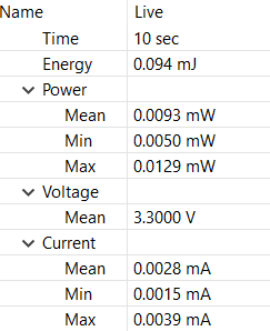
Here is the current test result, about 3 µA average current, under NO_OUTPUT mode, and removes the tantalum capacitor, the temperature sensor, and voltage divider resistors. Just used to show the power consumption of MSPM0.
 Figure 5-3 Current Consumption
Test