SLAAEE6 October 2023 MSPM0L1306 , MSPM0L1306
4 Gauge GUI Introduction
In this demo, a Gauge GUI will be used to record MCU data, run battery test case, and do data conversion. This GUI has two pages. First is MCU COM Tool, used to communicate with MSPM0 and record the MCU transmitted battery running data. Second is SM COM Tool, used to communicate with the source meter, run battery test case and record the test data sent from the source meter.
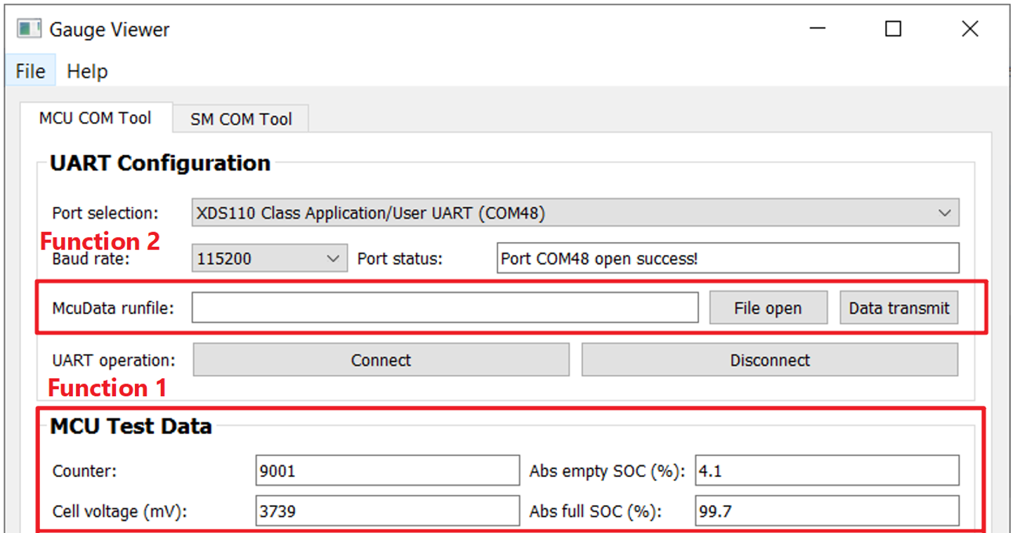
The used function for current detection is to receive the battery running data from MCU, shown in the function 1 of Figure 4-1. The data is saved automatically in excel with a name “time-McuData.xlsx”, after the battery test case settled in SM COM Tool is finished or you stop the test by pressing the "Disconnect" button.
 Figure 4-1 MCU COM Tool Function
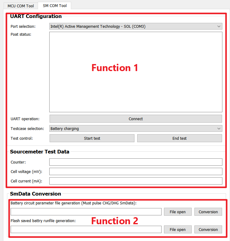
For the SM COM Tool, the used function for current detection is function 1, shown in Figure 4-2. It is used to control the source meter to run the battery testcase to test the current detection performance and show the data measured by source meter on the GUI. After the test is finished, the record data sent from source meter is saved in excel with a name “time-SmData.xlsx”. If you want to recreate this part, for the software, you need to at least install NI_VISA. For hardware, you need to buy a USB to rs232 wire and a keithley 2602A source meter.
 Figure 4-2 SM COM Tool Function