SLAAEE7 September 2024 MSPM0G3507
7 Design Results
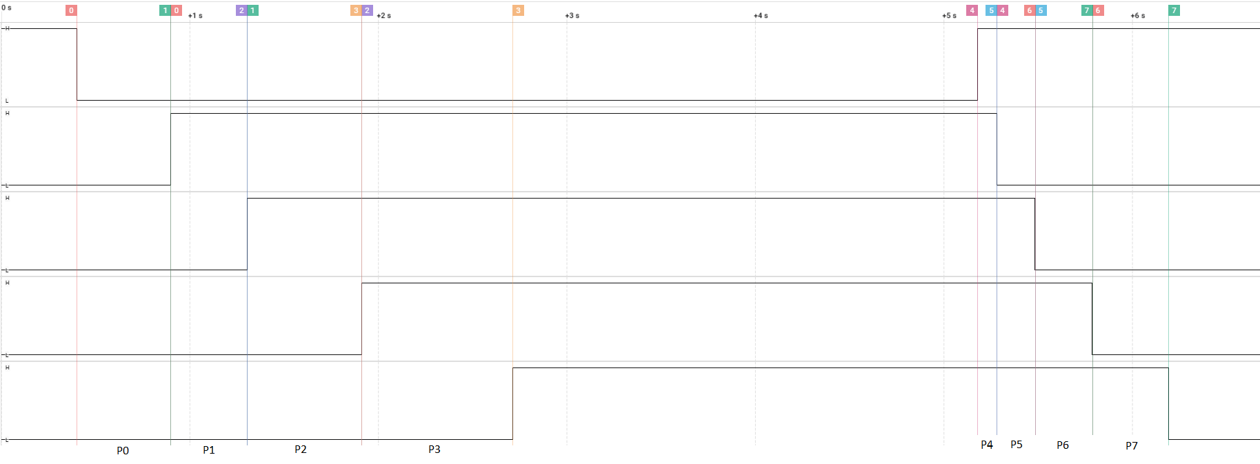
Figure 7-1 shows the logic graph results from executing the code example. The end is assuming the pins are also turned off in sequence.
 Figure 7-1 Sequence Result Graph
- P0: 498.6ms (2.01Hz)
- P1: 404.72ms (2.47Hz)
- P2: 607.12ms (1.65Hz)
- P3: 801.68ms (1.25Hz)
- P4: 102. 28ms (9.78Hz)
- P5: 202.36ms (4.94Hz)
- P6: 303.56ms (3.29Hz)
- P7: 404.72ms (2.47Hz)