SLAAEF5 March 2024 MSPM0G1505 , MSPM0G1505 , MSPM0G1506 , MSPM0G1506 , MSPM0G1507 , MSPM0G1507 , MSPM0L1303 , MSPM0L1303 , MSPM0L1304 , MSPM0L1304 , MSPM0L1304-Q1 , MSPM0L1304-Q1 , MSPM0L1305 , MSPM0L1305 , MSPM0L1305-Q1 , MSPM0L1305-Q1 , MSPM0L1306 , MSPM0L1306 , MSPM0L1306-Q1 , MSPM0L1306-Q1
- 1
- Abstract
- Trademarks
- 1Introduction
- 2Algorithm Introduction
- 3Gauge GUI Introduction
- 4MSPM0 Gauge Evaluation Steps
- 5MSPM0 Gauge Solutions
- 6References
5.1.3.1 Performance Test
Here is the test based on a 3200 mAh LiCO2 battery, under 25°C. u16MaxFullChgVoltThd setting is 4200mV. EmptyDhgVoltThd setting is 3000 mV.
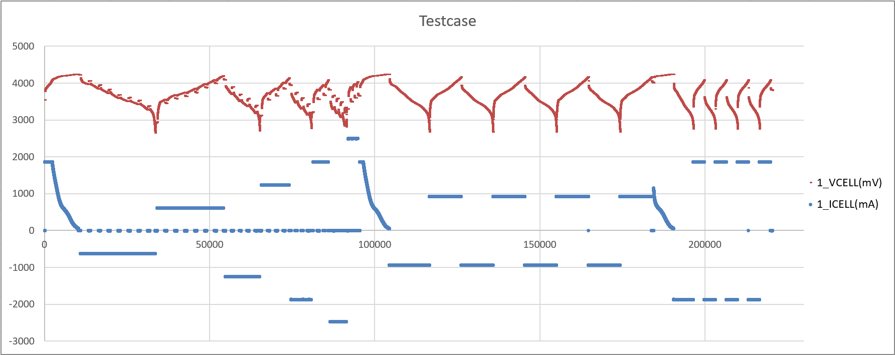
Here is the test pattern:
- Do pulse discharge and pulse charge with different load.
- Constant charge and discharge without rest for 4 cycles with different load .
 Figure 5-7 Battery Test Case
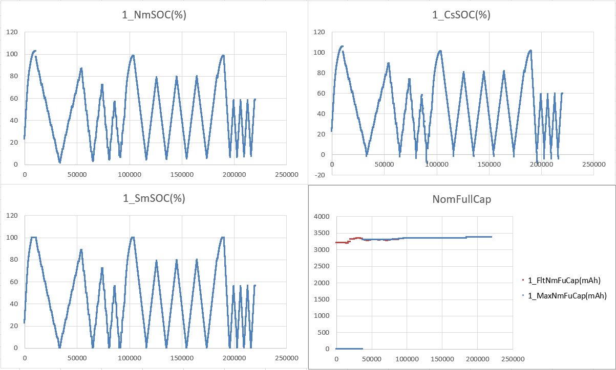
At the beginning there is an obvious gap for NomSOC, CusSOC and SmoothSOC. See the test results in Figure 5-8. It is caused from first OCV calibration error.
You can find the CusSOC has some gaps at the end of discharge, it is because the influence of EmptySOC. For SmoothSOC, it is flat and no jump at battery rest. All the data is controlled in the 0% to 100% range.
For different NomFullCap, the FltNomFullCap is updated almost after every rest. With the digital filter help, the NomFullCap will get more and more accuracy. After the MaxNomFullCap changes from 0 to a value, it means the output NomFullCap has an acceptable accuracy.
 Figure 5-8 Battery Test Result
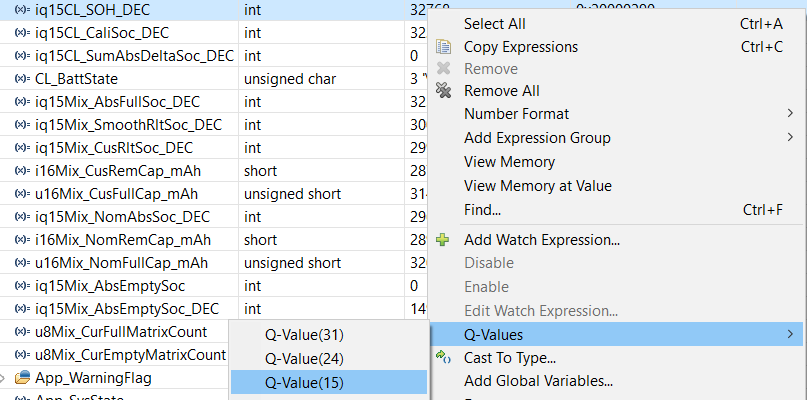
If you want to check more parameters under debug mode with Q format, you need to right click the value and select the related Q-Value format.
 Figure 5-9 Read Q Values