SLAAEF5 March 2024 MSPM0G1505 , MSPM0G1505 , MSPM0G1506 , MSPM0G1506 , MSPM0G1507 , MSPM0G1507 , MSPM0L1303 , MSPM0L1303 , MSPM0L1304 , MSPM0L1304 , MSPM0L1304-Q1 , MSPM0L1304-Q1 , MSPM0L1305 , MSPM0L1305 , MSPM0L1305-Q1 , MSPM0L1305-Q1 , MSPM0L1306 , MSPM0L1306 , MSPM0L1306-Q1 , MSPM0L1306-Q1
- 1
- Abstract
- Trademarks
- 1Introduction
- 2Algorithm Introduction
- 3Gauge GUI Introduction
- 4MSPM0 Gauge Evaluation Steps
- 5MSPM0 Gauge Solutions
- 6References
4.3 Step3: Input Customized Configuration
First, you need to make some system change based on your applications in “Gauge_UserConfig.h”. The common changed parameters are shown in Figure 4-7.
 Figure 4-7 Gaugge_UserConfig.h
Setting
Figure 4-7 Gaugge_UserConfig.h
SettingThe explanation of these parameters is shown in Table 4-3.
| Parameters | Comment |
|---|---|
| DETECTION_MODE | Affect the algorithm data input source, described in Section 4.4. |
| OUTPUT_MODE | Control whether to output tested data to GUI, described in Section 4.4. |
| CELL_NUMBER | The cell numbers for the battery pack. |
| CIRCUIT_TABLE_LENGTH | circuitParamsTable length. |
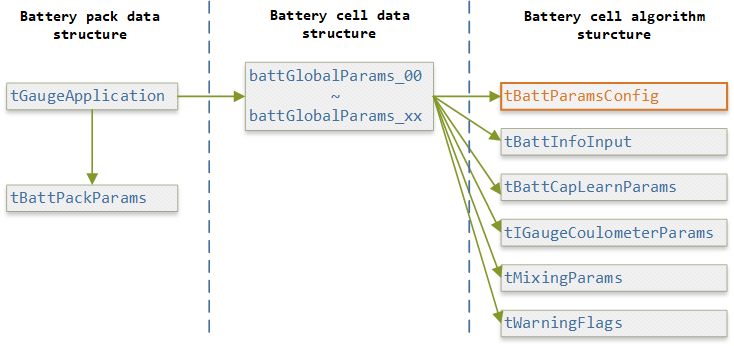
Second, you need to fulfill the data structure configuration in “Gauge_UserConfig.c”. A brief introduction to the used data structure in this gauge solution is shown in Figure 4-8.
"tGaugeApplication" represents the battery pack. All the pack related results are saved in "tBattPackParams".
"battGlobalParams_xx" represents every battery cell in the battery pack. All the algorithm data structures are all under it. You need to create the "battGlobalParams_xx" structure same as the battery numbers, and hang it under the "tGaugeApplication", through "battGlobalParamsArray".
 Figure 4-8 Data Structure
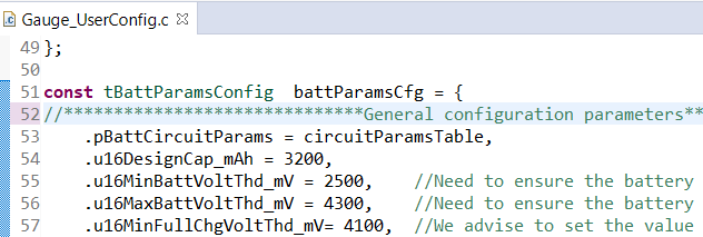
The most important data structure is “tBattParamsConfig”, shown in Figure 4-9. It contains all the battery parameter settings and algorithm settings.
 Figure 4-9 tBattParamsConfig
Structure
Figure 4-9 tBattParamsConfig
StructureFor easy evaluation, you only need to change the general configuration parameters. These parameters are divided into five parts. A short description is provided for all these related parameters.
| Parameters | Comment |
|---|---|
| u16DesignCap_mAh | Design capacity. Just input the standard capacity of battery or the tested one through battery parameter generation test. |
| u16MinBattVoltThd_mV / u16MaxBattVoltThd_mV i16MaxChgCurtThd_mA / i16MinDhgCurtThd_mA i8MaxChgTempThd_C / i8MinChgTempThd_C i8MaxDhgTempThd_C / i8MinDhgTempThd_C |
Battery Vcell, Icell and Tcell threshold. They are reserved to control warning flags when the battery situation is above these parameters. |
| u16MinFullChgVoltThd_mV u16MaxFullChgVoltThd_mVi16FullChgCurtThd_mA |
Battery full related setting. The battery charge voltage should be in this range. u16MinFullChgVoltThd_mV will help to judge when the battery is full. u16MaxFullChgVoltThd_mV will be used as default Full OCV after MCU power on. When the current is below than i16FullChgCurtThd_mA and the voltage is above u16MinFullChgVoltThd_mV, we will treat the battery is full. |
| u16EmptyDhgVoltThd_mV | When voltage reaches this value, we treat battery is empty. |
| u8AvgBattParamsUpdateCount | The average data will be obtained after the settled cycles. |
| Parameters | Comment |
|---|---|
| i8TempThdx_Ci16CurtThdx_mA | The current and temperature threshold for iq15AbsEmptySocMatrixInput[], iq15AbsEmptySocMatrix[], iq15AbsFullSocMatrix[]. Only for emptySoc, is input provided. You can use divide range you want according to Section 2.3.4. |
| iq15AbsEmptySocMatrixInput[] | The pretested EmptySoc matrix input. If all is 0, u16EmptyDhgVoltThd_mV is used as the empty OCV to calculate a related EmptySoc. Then, it will be auto learned after cycling. |
| Parameters | Comment |
|---|---|
| i16UnloadCurtLowThd_mA i16UnloadCurtHighThd_mA |
If the
current is between this range, the battery will be treated as rest.
Remember to consider the noise of current detection. Otherwise the rest detection will have problem. |
| u8SOHCalcCycleThd | The battery discharge cycle threshold to do SOH calculation. |
| iq15DefaultSOH_DEC | Battery default SOH value. |
| Parameters | Comment |
|---|---|
| u8CircuitTableLength | Circuit table length. |
| u8CircuitTableTestTemp_C iq15RcellNegTshift_R iq15RcellPosTshift_R |
These parameters are used to evaluate the Rcell under different temperatures. It is by experience and will not affect the performance too much. |
| Parameters | Comment |
|---|---|
| i16AvgLeckageCurt_mA | Internal leakage current compensation. |
| i16PassiveDhgCurt_mA | This is reserved for passive discharge current condition. |