SLAAEG3 August 2024 TAC5111-Q1 , TAC5212-Q1 , TAC5311-Q1 , TAC5312-Q1 , TAC5411-Q1 , TAC5412-Q1 , TAD5212-Q1
5 Application Example
In this example, there are two TAC5412Q1EVM's connected for ICLA synchronization with the distortion limiter enabled on each device. Two independent DC power generators supply VBAT_IN on each device. Figure 5-1 showcases the block diagram of the TAC5412-Q1 devices connected for ICLA functionality.
 Figure 5-1 EVM Test Setup
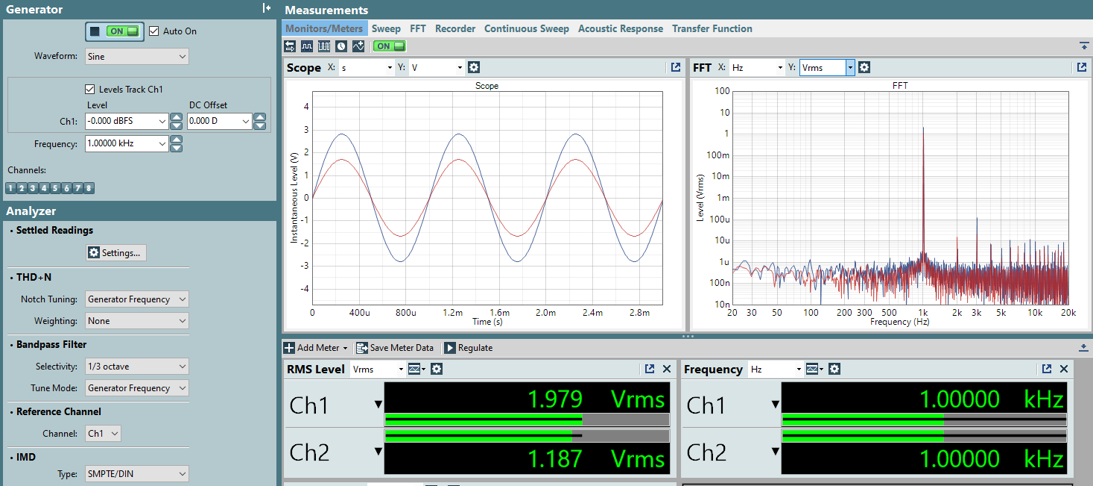
Both TAC5412Q1EVM's have the distortion limiter enabled, EVM1 is configured to an output level maximum threshold of 0dB and EVM2 has a maximum threshold set to -5dB. The inflection point, which triggers the engagement of the distortion limiter, is configured to 9V on each device. VBAT1 and VBAT2 on each device are measured above the inflection point at 12V. Figure 5-2 shows the output level of each device with ICLA disabled and DOUT unconnected between EVM1 and EVM2.
 Figure 5-2 Output Waveform, ICLA Disabled, DOUT Unconnected
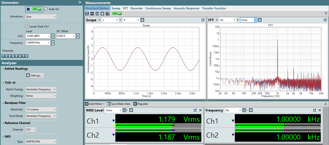
Figure 5-3 shows the output level of each device with DOUT connected between EVM1 and EVM2 and ICLA enabled. The limiter maximum threshold is aligned on both EVM's, as a -5dB attenuation is applied to the output signal level. VBAT1 and VBAT2 remain above the inflection point at 12V.
 Figure 5-3 Output Waveform, ICLA Enabled, DOUT Connected
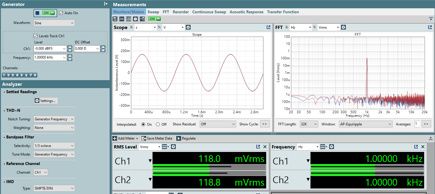
The limiter minimum threshold is set to -25dB and -50dB on EVM1 and EVM2 respectively. As VBAT1 decreases below the inflection point, the output level of both devices is attenuated to 118 mVrms, an attenuation close to -25dB, which is expected according ICLA settings.
 Figure 5-4 Output Waveform, -25dB Attenuation
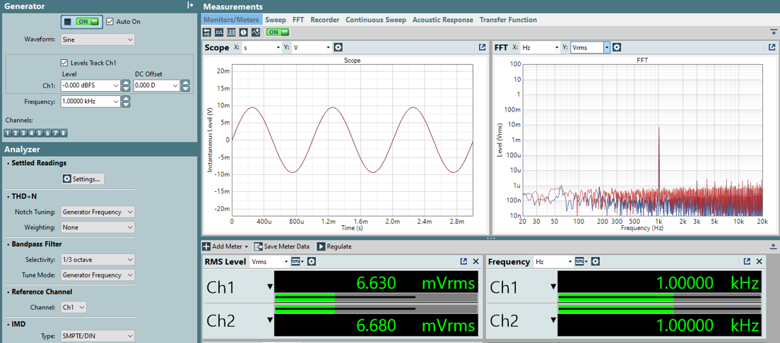
Shown in Figure 5-5, as VBAT2 decreases below the inflection point to 8V, the output attenuates to approximately 6.6 mVrms, an attenuation close to-50dB, which is expected according to ICLA settings.
 Figure 5-5 Output Waveform, -50dB Attenuation
As shown in the waveforms, the output channels of the DAC can have a difference measured less than 0.1dB with respect to full-scale when connected for ICLA synchronization.