SLAAEG7 April   2024 TAC5111 , TAC5111-Q1 , TAC5112 , TAC5112-Q1 , TAC5211 , TAC5212 , TAC5212-Q1 , TAD5112 , TAD5112-Q1 , TAD5212 , TAD5212-Q1


  1.   1
  2.   Abstract
  3.   Trademarks
  4. 1Headset Plugs and Connection Diagrams
    1. 1.1 Part I: Pseudo-Differential (Capacitor-less) Headset Output Configuration
      1. 1.1.1 Detection Block, Capacitor-less Interface
      2. 1.1.2 How to Determine the Comparator Threshold V1 and V2 (Capacitor-less Interface)
      3. 1.1.3 How Does the Bias Voltage Vary With Detection Mode?
      4. 1.1.4 Detection Sequence – Capacitor-less Interface
    2. 1.2 Part II: AC-Coupled Stereo Headset Output Configuration – Capacitor Interface
      1. 1.2.1 Detection Block – Capacitor Interface
      2. 1.2.2 How to Determine the Comparator Threshold V1 and V2 – Capacitor Interface
      3. 1.2.3 How Does the Bias Voltage Change With Detection Mode?
      4. 1.2.4 Detection Sequence – Capacitor Interface
  5. 2Example for a Pseudo-Differential (Capacitor-less) Output Configuration
  6. 3Example for an AC-Coupled (Capacitor) Output Configuration
  7. 4Flowchart for Pseudo-Differential (Capacitor-less) Output Configuration
  8. 5Flowchart for AC-Coupled (Capacitor) Output Configuration
  9. 6Summary
  10. 7References

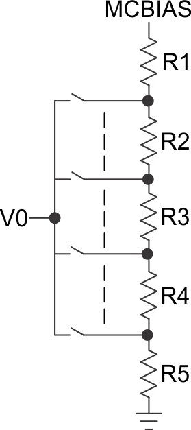
How to Determine the Comparator Threshold V1 and V2 – Capacitor Interface

GUID-20231122-SS0I-7CT1-XWHD-DBBFSGNS0QTG-low.gif
V 1 = ( M I C B I A S - r e f ) × 11 100 + r e f     o r   V 1 = ( M I C B I A S - r e f ) × 1 5 + r e f V 2 = ( M I C B I A S - r e f ) × 4 5 + r e f       r e f = V S S = 0 V M I C B I A S   v a r i e s   w i t h   d e t e c t i o n   m o d e

Note that for V1 and V2 there will be a lot more threshold possible than the ones shown previously which can be based on eternal resistor and ADC loading.