SLAAEI4 August   2024 TAC5111-Q1 , TAC5212-Q1 , TAC5311-Q1 , TAC5312-Q1 , TAC5411-Q1 , TAC5412-Q1 , TAD5212-Q1


  1.   1
  2.   Abstract
  3.   Trademarks
  4. 1Introduction
  5. 2Signal Processing Chain
  6. 3Distortion Limiter
    1. 3.1 Distortion Limiter Parameters
      1. 3.1.1 Threshold Maximum
      2. 3.1.2 Threshold Minimum
      3. 3.1.3 Inflection Point
      4. 3.1.4 Slope
      5. 3.1.5 Attack Rate
      6. 3.1.6 Release Rate
      7. 3.1.7 Hold Counter
    2. 3.2 Limiter Response
  7. 4Brown-Out Protection
    1. 4.1 Brown-Out Protection Parameters
      1. 4.1.1 Critical Level
      2. 4.1.2 Gain Level
      3. 4.1.3 Attack Rate
      4. 4.1.4 Release Rate
      5. 4.1.5 Hold Counter
    2. 4.2 Brown-Out Protection Response
  8. 5Thermal Foldback
    1. 5.1 Thermal Foldback Parameters
      1. 5.1.1 Temperature Threshold
      2. 5.1.2 Maximum Attenuation Threshold
      3. 5.1.3 Slope
      4. 5.1.4 Attack Coefficient
      5. 5.1.5 Release Coefficient
      6. 5.1.6 Hold Counter
        1. 5.1.6.1 Thermal Foldback Response
  9. 6Example
  10. 7Summary
  11. 8References

Brown-Out Protection Response

Figure 4-3 is an example of the BOP algorithm engaging with the following parameters:
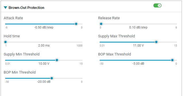
 BOP PPC3 Configuration Figure 4-3 BOP PPC3 Configuration

Figure 4-4 features an incoming audio signal subject to the parameters of the BOP algorithm. VBAT is dropping from 11V to 10V at the first negative edge of channel two and subsequently the analog output is attenuated to a -3dB signal. As VBAT continues to drop below 10V the output further attenuates to the BOP minimum threshold, a -20dB signal.
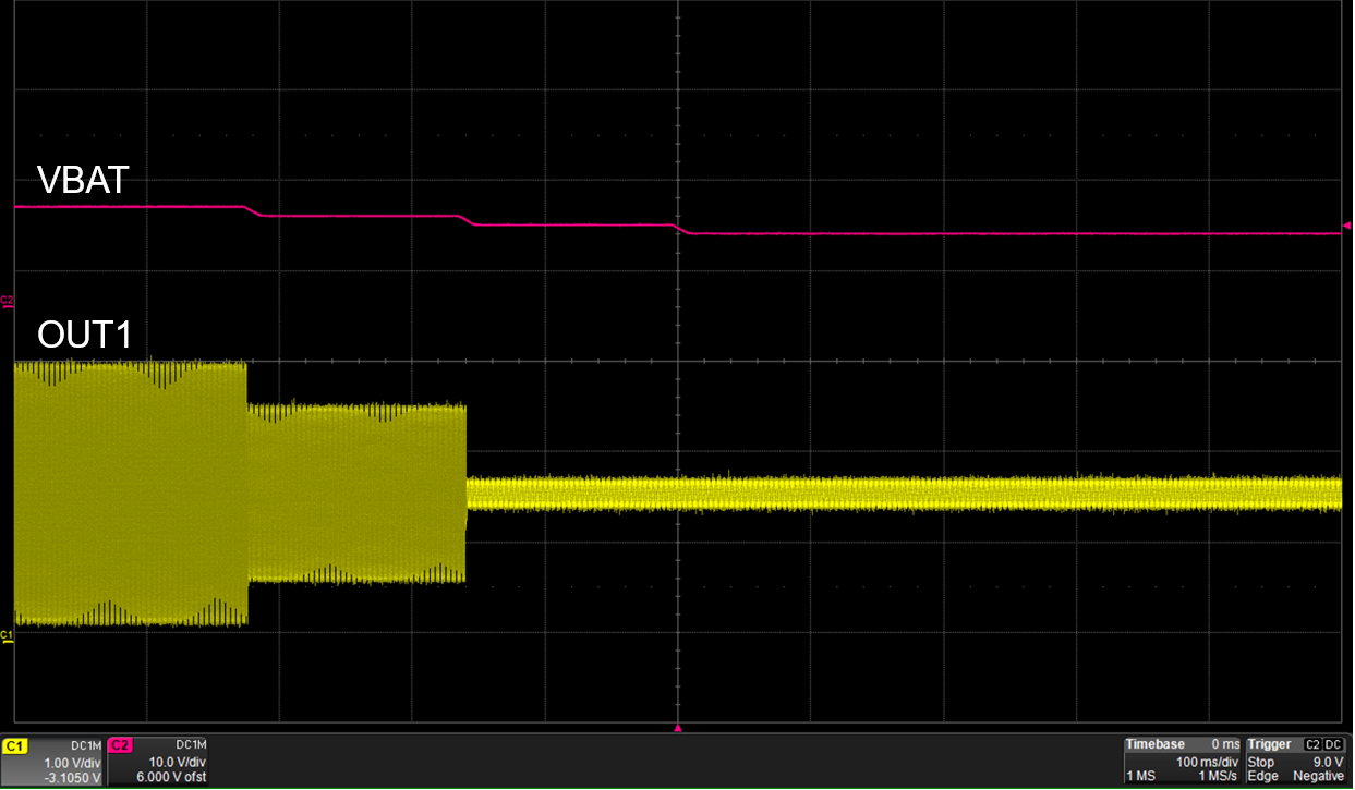
 Two Stage BOP Response Figure 4-4 Two Stage BOP Response